Every laminated busbar leaves the factory after a dielectric test. Very few buyers can say what voltage was applied, for how long, at what ramp rate, and whether the leakage current was recorded. Those four facts are the difference between a test that protects the customer and a stamp on a route card.
Every laminated busbar leaves the factory after a dielectric test. Very few buyers can say what voltage was applied, for how long, at what ramp rate, and whether the leakage current was recorded. Those four facts are the difference between a test that protects the customer and a stamp on a route card.
A dielectric withstand test applies a voltage above the operating voltage for a defined time and observes whether the insulation breaks down. It is a go/no-go check for gross defects: a pinhole in a film, a conductive path along an edge, a void that ionises at the test stress, or a foreign object bridging the layers.
What it does not prove is endurance. A bar that survives 60 seconds at the test voltage may still contain voids that discharge at a lower voltage for years, slowly eroding the dielectric until the insulation fails in service. That gap is why partial discharge measurement exists, and why a hipot-only acceptance standard is incomplete for any bar that will see a continuous high field.
The test is also not a substitute for construction quality. A well-built bar passes easily; a poorly built bar may pass by luck and fail on the next unit. The test protects the customer from the bad unit, not from the bad process.
The design-side view of discharge-free construction is in partial discharge free design.
The test voltage is derived from the rated insulation voltage of the assembly and the standard the assembly is built to, not chosen by the fabricator. For low-voltage switchgear and controlgear assemblies, IEC 61439-1 defines dielectric properties and the corresponding verification, and the test values scale with the rated insulation voltage rather than with the working voltage of the application.
The practical consequence is that a bar rated for a 1,000 V DC link is tested at a value well above 1,000 V — commonly in the low kilovolt range — because the test is intended to prove margin, not to reproduce operating stress. Using the operating voltage as the test voltage is a common mistake in internally written specifications, and it produces a test that almost nothing fails.
For components within a certified assembly, the assembly's certification may define the routine test, and the component supplier's test should be consistent with it rather than invented separately. When the customer's standard and the fabricator's habit disagree, the drawing should cite the standard and the clause, so the disagreement is resolved on paper before the first shipment.
The standard framework is indexed in the standards hub.
AC test voltage is the conventional choice because it stresses the insulation in both polarities and is easier to generate at the required level. DC testing is used where the insulation system will actually operate under DC, and where the capacitance of a large laminated stack makes AC testing impractical or where the DC field distribution matters.
The two are not equivalent. A DC test at the same peak value applies a constant stress that can charge interfaces and produce a field distribution different from AC, and it can miss defects that respond to polarity reversal. An AC test at the same RMS value applies a higher peak, which is why standards specify which one they mean and at what value.
For a busbar that will live on a DC link, there is an argument for testing both: an AC routine test for defect detection, and a DC test or a DC-biased partial discharge measurement to characterise behaviour under the actual operating field. The second is not a production test; it is a design qualification test, and it belongs in the type-test record.
A test that applies the full voltage in a step charges the insulation abruptly and can produce a transient that either trips the leakage limit or, worse, initiates a discharge that would not occur under a controlled ramp. Standards typically specify a ramp over a few seconds, a hold at the test level for a defined duration — commonly one minute for type tests and a shorter period for routine tests — and a controlled discharge at the end.
The hold time exists to let slow processes develop. A void that is going to ionise will usually do so within the first seconds; a surface path that is going to track needs longer. A one-second routine test is a production convenience, and it is adequate only when the process is stable and the design has already been type-tested at the full duration.
The discharge at the end matters for operator safety and for the next test. A laminated stack with a large layer-to-layer capacitance holds charge after the supply is removed, and a bar that is handled before discharge can deliver a shock or a spark that damages the insulation surface. The test fixture should include a discharge resistor and a visible indication that the circuit is dead.
Buyer-side acceptance scope is discussed in the quote comparison framework.
Most hipot sets display a leakage current, and most operators only look at the pass light. The leakage value is the more informative number: a bar with a stable, low leakage through the hold period is behaving like a capacitor, while a bar whose leakage climbs steadily is showing an ionising defect or a surface path heating up.
A useful acceptance standard records the leakage at the start and end of the hold and sets a maximum, plus a rule that the value must not rise by more than a defined percentage. That rule catches the bar that passes the go/no-go threshold but is on its way to failure.
Leakage also depends on humidity and temperature. A test performed in a dry, cool room can understate the leakage that the same bar would show in a humid container. If the acceptance limit is tight, the test condition should be recorded, and the limit should be set with the worst expected environment in mind.

Partial discharge is a localised breakdown that does not bridge the insulation. It occurs in voids, at conductor edges, along delaminated interfaces and at the boundaries between materials with different permittivity. Each event transfers a small charge, and the cumulative effect over years erodes the dielectric until it fails.
The measurement is expressed in picocoulombs, and the acceptance limit is set at a defined multiple of the operating voltage — commonly 1.2 to 1.5 times — with a specified background noise floor. A bar that shows no discharge above, say, 5 pC at 1.2 times operating voltage is a different product from one that shows 50 pC.
The measurement is sensitive to the test arrangement: the coupling capacitor, the shielding, the grounding and the ambient noise all affect the result. A partial discharge test performed on a bench next to a welding set is not a measurement; it is a number. The fixture and the background level belong in the test record.
The application-level treatment is in partial discharge.
Four sites account for most discharge activity. The edge of the conductor foil, where the field concentrates and the film is thin. The interface between the film and the potting or coating, where a void can form during cure. The terminal end, where the conductor geometry changes abruptly and the insulation is often thinner. And any drilled hole or cut edge where a burr or a delamination creates a gas pocket.
Designing against these is a matter of geometry and process: rounding the foil edge where the field is highest, controlling the overlap at the boundary, ensuring the potting wets the surface without trapping air, and keeping the terminal transition gradual rather than stepped.
The process controls that matter are cleanliness before lamination, controlled press cycles, and a cure profile that does not outgas into the stack. A void that forms during cure is invisible to a hipot test and visible to a partial discharge measurement, which is the argument for doing both on the first article of every new stack design.
Material and layer choices that move the inception voltage are in dielectric selection.
A dielectric test on a busbar is a high-energy test, and the fixture should treat it that way: an enclosure or interlocked guard, a discharge path, a clear indication of test state, and a procedure that prevents a second person from touching the bar during the hold. The test leads should be rated for the voltage and current, and the return path should be solid, because a floating return produces erratic leakage readings.
The bar should be tested in a condition that reflects its mounted state as far as possible. Testing a bare bar in air and then installing it against a metal enclosure with a small air gap tests two different insulation systems. If the installation relies on the enclosure for clearance, the test fixture should include a grounded plane at the specified distance.
For production, the fixture should also protect the bar: contact points that do not scratch the plating, supports that do not deform the stack, and a handling procedure that keeps the terminals off the bench. A test that damages the part is not a quality gate.
Product-side construction details are on the power electronics busbar pages.
A production acceptance standard for dielectric integrity has three tiers. Every unit: a routine withstand test at the specified voltage and duration, with leakage recorded and a maximum limit. Every lot: a partial discharge sample at the defined voltage multiple, with the sample size set by the process stability. Every design or process change: a type test at the full duration, with PD measurement and a breakdown test on a sacrificial sample.
The pass criteria should be stated as numbers rather than descriptions. "No breakdown and leakage below X mA at Y kV for Z seconds" is auditable. "Insulation in good condition" is not.
The rework rule matters as much as the criterion. A bar that fails a hipot test has usually been damaged internally, and re-testing after drying or cleaning does not restore the insulation. The correct disposition is scrap or engineering review, not a second attempt.
Routine and type-test practice on the line is described on the quality page.
As busbars move into 800 VDC racks and medium-voltage solid-state transformer front ends, the dielectric acceptance standard has to change in three ways. The test voltage rises with the rated insulation voltage, which raises the energy in the test and the importance of the fixture. The partial discharge criterion becomes mandatory rather than optional, because a continuous DC field makes discharge erosion a life-limiting mechanism.
The third change is the condition of the test. At medium voltage, surface contamination and humidity dominate the surface withstand, so a dry factory test can pass a bar that fails in a humid installation. The standard should include a humidity-conditioned test on a sample, or a surface leakage criterion measured after conditioning.
The materials follow the same logic. PET, Nomex and DLF coating all behave differently under continuous field, and the qualification should be run on the actual material stack rather than on a generic coupon. A material that passes at 400 V is not automatically qualified at 800 V, even at the same dielectric thickness, because the field distribution and the partial discharge inception voltage change.
The 800 VDC rack case is covered in 800 VDC data center busbars, and the medium-voltage case in solid-state transformer busbars.
The test record should let a reader reconstruct the test without asking a question: the part number and serial or lot, the test standard and clause, the applied voltage, the ramp rate, the hold time, the leakage at start and end, the pass or fail, the instrument identification and calibration date, the ambient temperature and humidity, the operator and the date.
For partial discharge, the record adds the test voltage multiple, the measured quantity, the background noise level and the fixture description. For a type test, it adds the breakdown voltage and the location of the failure, which is the information that improves the next design.
This record is also what a customer's audit will ask for, and what a certification body will want to see when the assembly is submitted. A fabricator who can produce it without reconstructing the shift is a fabricator who has a process, not just a tester.
Traceability expectations are set out in battery passport traceability.
A unit that fails at the routine voltage usually has a gross defect: a pinhole, a conductive burr, a film damaged during handling, or a lamination void at the edge. The location of the failure tells you which. A failure at the terminal end points to machining or assembly damage; a failure along an edge points to registration or trimming.
A unit that passes the routine test but shows high partial discharge has a smaller defect: an interface void, a delamination that has not bridged, or a contaminated surface. This is the more insidious failure because it passes the gate and fails in service. The response is to increase the sample rate and inspect the process, not to tighten the hipot voltage, which will not find it.
A unit that passes cold and fails after thermal cycling has a void that opens with expansion. That pattern belongs in the type test, and the fix is usually in the lamination or potting process rather than in the material selection.
For the mechanical side of the same joint, see torque and pull acceptance and busbar connections.
A dielectric test set that reads 3 percent low is a test set that passes bars it should fail. Calibration is therefore part of the acceptance standard rather than a maintenance detail: the instrument should be calibrated against a reference at a defined interval, and the calibration certificate should be traceable and available at audit.
For production, the more useful control is a daily verification with a known artefact — a reference capacitor or a test box with a defined leakage — that confirms the set is behaving before the shift starts. A set that fails the morning check is taken out of service, which is cheaper than discovering the drift after a shipment.
Partial discharge measurement has a second calibration dimension: the background noise level has to be measured with the fixture energised and the bar disconnected, and the acceptance limit has to sit comfortably above that floor. A limit set at 5 pC in a room with 8 pC of background noise is a limit that either fails everything or is quietly ignored.
The frequency of testing follows risk. Routine tests on every unit, partial discharge on a lot sample, full type tests on design and process changes, and a periodic re-qualification — annually, or after a material or process change — keeps the standard alive rather than freezing it at the day the drawing was released. A standard that is never revisited tends to describe the process as it was, not as it is.
A buyer qualifying a busbar supplier for a high-voltage application can learn most of what matters from three records. The first is the type-test report for the specific stack design, not for a similar part: applied voltage, hold time, partial discharge level, breakdown location and the fixture description. A report without the fixture description cannot be reproduced.
The second is the routine-test record for a recent lot, showing the leakage values rather than only the pass stamp, and the instrument calibration status. A lot record with a single pass line and no numbers is a record that was written after the fact.
The third is the change log for the last two years, covering material, process and fixture changes. A supplier who has changed a film supplier or a potting compound without re-running the type test has an unqualified product, even if every routine test since has passed.
Those three records take an afternoon to review and answer the questions that a factory tour cannot: whether the design was qualified, whether the production test produces data, and whether change is controlled. For an 800 VDC or medium-voltage program, they are worth requesting before the RFQ rather than after the first shipment.
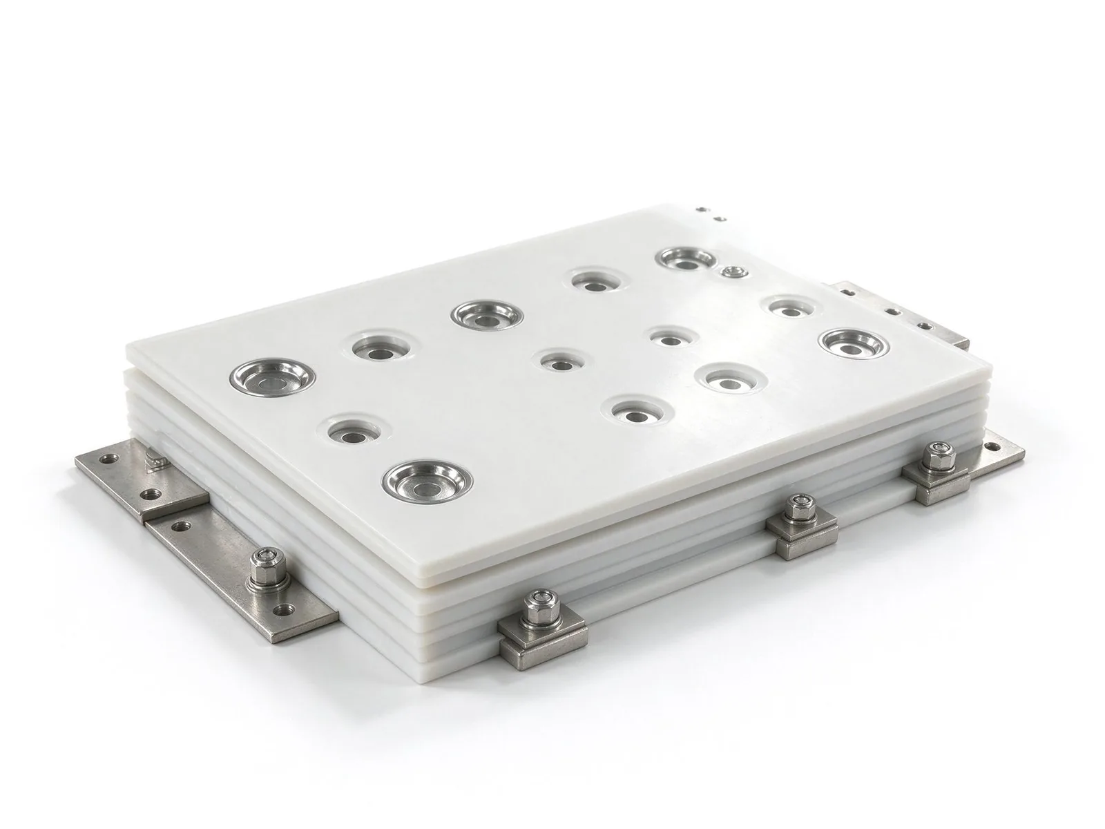
A busbar fails quietly when a void inside its insulation starts discharging. This guide co
Read article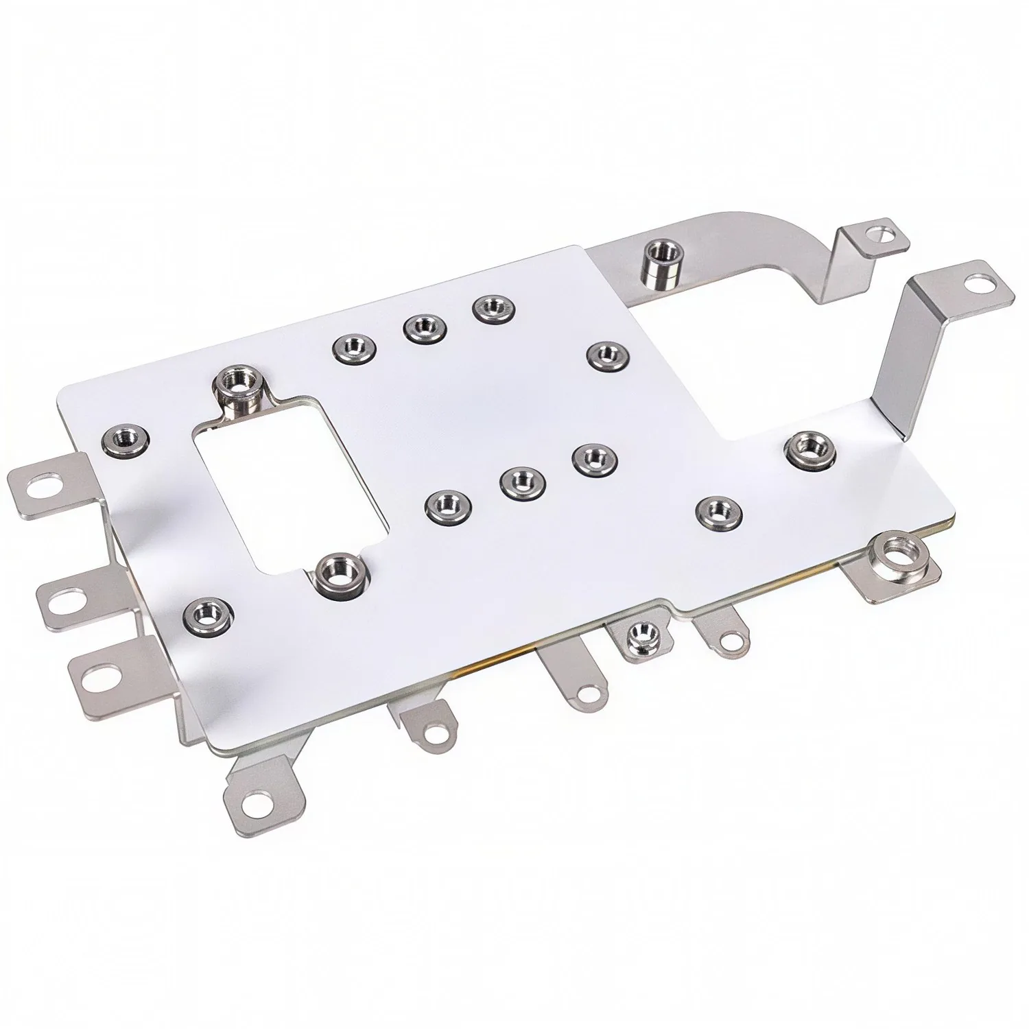
A joint that is tight is not the same as a joint that is correct. Torque windows, pull lim
Read article
Sofia Lindqvist is a high-voltage test and partial discharge engineer with 8 years in dielectric qualification of laminated busbars. She runs IEC 60270 partial-discharge measurement, withstand-voltage and insulation diagnostics, and helped build SHANYUAN's in-house HV test lab. She holds an M.S
Send the current profile, voltage class and terminal types — our engineers reply within one business day.
