A 4,000 A switchboard built to UL 891 and a 4,000 A assembly built to IEC 61439-2 can look identical on a pallet and behave completely differently under a 65 kA fault. The difference is documentation, and it starts at the busbar. This article works through the UL documents that govern a US switchboard, the NEC clauses that decide whether the assembly rating holds, what a 100 kA fault does to a bar mechanically, and the eight items that must be settled before a US-bound bar is quoted.
A 4,000 A switchboard built to UL 891 and a 4,000 A assembly built to IEC 61439-2 can look identical on a pallet and behave completely differently under a 65 kA fault. The difference is documentation, and it starts at the busbar. This article works through the UL documents that govern a US switchboard, the NEC clauses that decide whether the assembly rating holds, what a 100 kA fault does to a bar mechanically, and the eight items that must be settled before a US-bound bar is quoted.
This page is an annual rolling data page: the 2026 edition, refreshed once a year as new market data is published.
A European panel builder and a US panel builder can both be looking at a 4,000 A low-voltage switchboard with tin-plated copper bars, and they will still be designing two different products. The reason is not patriotism. It is that the two markets certify the assembly against different documents, and those documents disagree about who carries the short-circuit rating, what ambient temperature the ampacity is based on, and how much temperature rise a joint is allowed.
In the IEC world, IEC 61439-1 and -2 treat the assembly as a type-tested unit: the busbar current is verified by a temperature-rise test on the actual arrangement, and the short-circuit withstand is verified by test or by calculation against the assembly's own rating. In the US world, UL 891 covers switchboards, UL 857 covers busways, UL 67 covers panelboards, and UL 508A covers industrial control panels. Each has its own temperature-rise table, its own short-circuit test programme, and its own labelling rules.
The practical consequence for a buyer in Texas or Ohio is that the bar that was perfectly adequate in an IEC 61439 assembly may need to be a size larger, or a joint may need a different bolt, or the assembly may need a higher SCCR than the sum of its breakers. Getting this wrong does not show up at commissioning. It shows up at the first inspection, or at the first fault.
For a laminated or solid copper bar supplier, this matters commercially: the drawing package for a US switchboard usually specifies conductor size, plating, hole pattern, and torque values that were derived from UL tables, not from IEC tables. Quoting against the wrong table is how a shipment of correct-looking bars gets rejected at receiving inspection. Earlier work on regional standards for busbar systems sets out the document map; this article deals with what the US documents actually require of the bar itself.
UL 891 applies to dead-front switchboards rated up to 6,000 A and 600 V, and it is the document that governs most service-entrance and distribution switchboards in commercial buildings. It defines temperature-rise limits by component, requires short-circuit testing of the busbar and connections at the assembly rating, and requires a short-circuit current rating label on the equipment. The busbar is not tested in isolation; it is tested inside a representative enclosure with representative breakers installed.
UL 857 applies to busways, the factory-built runway systems that carry power above a data hall or along a machine line. Its test regime focuses on the busway as a system: housing, insulators, joints, and end fittings. A laminated bar that behaves perfectly as a component can still fail a busway test if the joint hardware allows movement under fault.
UL 67 applies to panelboards and is the reason a 42-circuit panel with a 225 A bus is not simply a small switchboard. The temperature-rise table and the short-circuit test are scaled to the panel construction, and the busbar is usually a formed bar rather than a flat laminated stack.
UL 508A is the standard most industrial control panels are listed to, and it is the one that catches exporters most often. A 508A panel can use a bar with a short-circuit current rating based on the manufacturer's tested combination, and the panel's SCCR is then limited by the weakest component in the power circuit, including the busbar, the lug, and the terminal block. A high SCCR breaker does not raise the panel's rating on its own.
There is also UL 1558 for metal-enclosed low-voltage power circuit breaker switchgear, which is the equipment used in larger industrial and utility-adjacent installations. If you are quoting a bar for a switchgear lineup at a substation or a large plant, UL 1558 rather than UL 891 is often the governing document, and the short-circuit tests are more severe.
The single most common misunderstanding in US low-voltage work is that the short-circuit current rating belongs to the breaker. It does not. The rating that the inspector reads off the label is the rating of the assembly, and the assembly rating is the lowest rating in the current path at the conditions tested.
NEC 110.10 requires that the equipment's short-circuit current rating be adequate for the available fault current at the point of installation. NEC 240.86 then allows series ratings, where a current-limiting upstream device protects a lower-rated downstream device, but only under defined conditions and only if the combination is tested and marked. For a busbar supplier, the relevance is direct: if a panel builder is relying on a series rating to get a 65 kA label on a 22 kA frame, the busbar and its joints must still be part of the tested combination. Bars made to a drawing with different hole spacing, a different bolt size, or a different plating than the tested sample are not the tested combination.
This is where first-article inspection and a drawing-locked process pay for themselves. When a US customer asks whether your bar can be substituted into a listed assembly, the honest answer is that the assembly listing is the customer's and the substitution is permitted only within the manufacturer's own controlled documentation. Suppliers who understand that answer keep their customers out of trouble, and they also avoid casually promising an SCCR number they cannot support.
Fault current levels explain why this matters more in 2026 than in 2016. Dense urban networks and data centre campuses increasingly see 50–100 kA available at the service entrance, and utility fault levels rise as more inverter-based generation is added with low impedance behind the meter. A 22 kA assembly in a 65 kA location is not a documentation problem; it is an arc-flash and fire problem.
Steady-state ampacity and short-circuit withstand are unrelated design problems that happen to use the same piece of copper. A 100 kA symmetrical fault with a 2.3 peak factor produces a first-peak current near 230 kA, and the electromagnetic force between two parallel bars is proportional to the square of that current and inversely proportional to the spacing.
Put numbers on it. Two 40×10 mm bars carrying 230 kA peak, spaced 20 mm apart centre-to-centre, see forces on the order of tens of kilonewtons per metre of length. The bar does not fail because it melts; it fails because the support insulator cracks, the bar bends permanently, or the joint opens far enough to strike an arc. This is why the short-circuit test is a mechanical test as much as an electrical one, and why the mounting hole pattern and insulator spacing on a US drawing are not cosmetic.
Bracing strategy usually comes down to three choices: thicker bar with closer supports, a laminated stack that is stiffer in the plane of the force, or an insulating barrier that also acts as a mechanical restraint. All three change the part you are being asked to supply, and all three change the price. A supplier who only quotes thickness and width is quoting half a part.
The fault duration matters too. A 100 kA fault cleared in 30 ms has a much smaller thermal dose than the same fault cleared in 300 ms, but the mechanical peak arrives in the first half cycle and does not care about clearing time. That is why the first-peak rating appears separately on switchgear nameplates, and why a bar that passes a three-second withstand test can still fail on peak.
For the buyer, the practical request is: tell us the fault level, the clearing time, the support spacing, and whether the assembly was tested with barriers installed. Without those four values, a short-circuit claim is a guess dressed as a specification.
UL 891 sets temperature-rise limits for busbar and connections rather than a single assembly limit, and the values differ by material and by connection type. The familiar IEC 61439-1 approach caps the rise at 70 K for bare copper bars and gives separate values for tinned and silver-plated joints, measured against a 40 °C average ambient with a 24-hour profile. The US tables are structured differently but converge on the same physical reality: a joint is allowed less rise than the bar it connects.
That asymmetry is the whole design story. Insulation and bar ampacity are limited by the bar surface temperature, while a joint is limited by contact resistance and by the creep of the fastener under thermal cycling. A 1,000 A bar running at a 55 K rise is unremarkable; a joint on the same bar running at 75 K is a maintenance item.
Two calcs are worth carrying in your head. First, resistive loss scales with current squared, so a 10% overload adds 21% to the heat input and roughly 10 K to the surface rise in natural convection. Second, at 1,000 A a joint that measures 10 µΩ dissipates 10 W, and 10 W concentrated in a few square centimetres is the difference between a 40 K and an 80 K local rise.
This is why the plating specification on a US drawing is usually tin over copper, with a nickel barrier where the joint runs hot or where the environment is humid and sulfur-bearing. Tin at 6–12 µm over a 1–3 µm nickel barrier is the common industrial answer, and it is also why receiving inspection should include a plating thickness check on a sample, not only a visual check. The metallurgy of that joint is covered in more depth in the article on plating and corrosion behaviour of busbar joints.
A US switchboard is rated at a 40 °C ambient, but the room it sits in is often 35 °C with a 45 °C hotspot at the top of the lineup. Altitude derating starts above 2,000 m and is frequently forgotten in mountain-state projects. Enclosure type changes the heat transfer: a NEMA 1 ventilated enclosure behaves nothing like a NEMA 4X sealed stainless box, and a sealed box in direct sun can run 15 K above the room.
The correction method matters more than the correction value. For a naturally cooled bar, the surface rise is roughly proportional to the dissipated power divided by the exposed area, with a convection coefficient that depends on orientation. A vertical bar in a chimney-like enclosure cools better than a horizontal bar under a shelf, and a bar surrounded by other warm bars cools worse than an isolated one.
Where the assembly is sealed and the internal air is mixed, the honest approach is to treat the internal air as the ambient for the bar and to size the enclosure cooling to hold that air at the design value. Adding a fan does not fix a bar that is undersized by two sizes; it only moves the failure to the fan.
In practice, a US RFQ for a service-entrance switchboard will usually state the ambient, the enclosure type, the available fault current, and the required SCCR label. If any of those is missing, the correct move is to ask, because the answer changes the conductor section and sometimes the material. Our own ampacity reference tables assume natural convection in still air and should be corrected for the actual enclosure before selection.
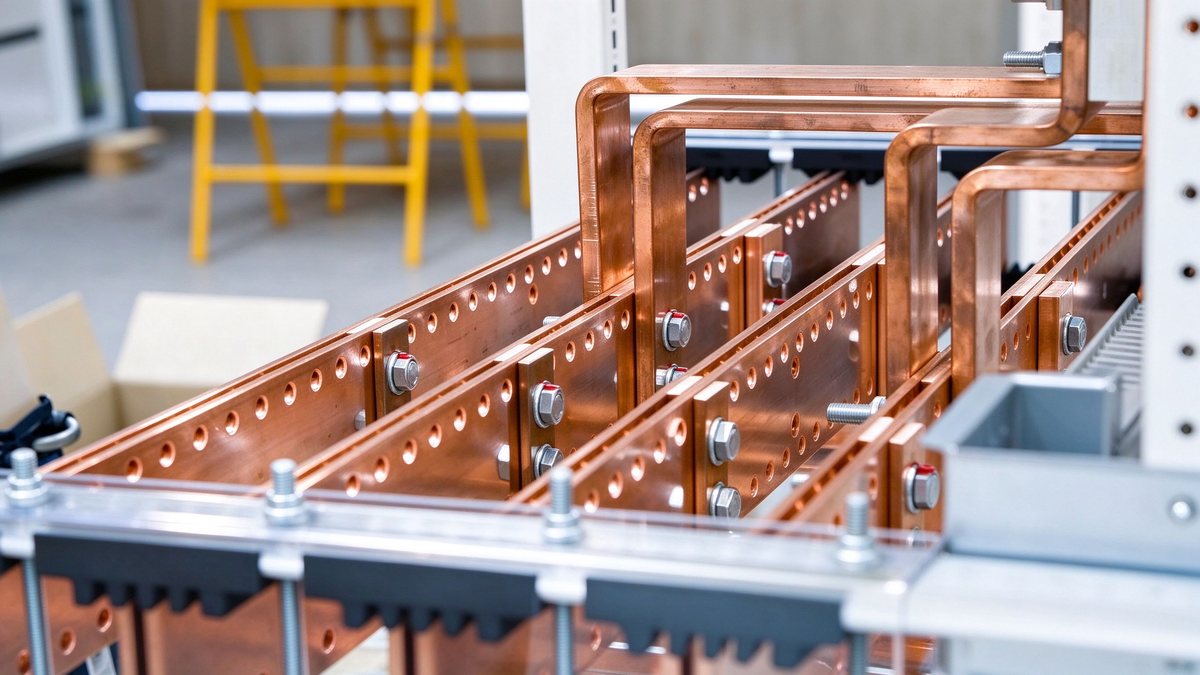
US distribution practice is more aluminium-tolerant than European practice, largely because 1350 series aluminium bar is cheaper per amp at large sections and because the US has a long history of aluminium service entrance equipment. That tolerance comes with two conditions that are often skipped: the aluminium must be the right alloy and temper, and the termination must be rated for aluminium.
For busbar, 1350-H12 or H14 is the common conductor grade, with conductivity around 61% IACS, versus roughly 100–101% IACS for C11000 ETP copper. That conductivity gap means an aluminium bar needs about 1.6 times the copper cross-section for the same loss, and the surface area penalty is smaller than the resistance penalty, so aluminium often runs cooler per amp than its reputation suggests.
The problems are at the interfaces. Aluminium forms an oxide that is resistive and grows quickly, it creeps under bolt load, and it is cathodic to copper, so a copper-to-aluminium joint in a wet environment will corrode the aluminium. The standard mitigations are tin plating on the aluminium, a bimetallic transition or a properly rated Al-Cu connector, and a joint design that maintains contact pressure through thermal cycling, usually with Belleville or conical washers.
In a UL assembly, the decisive question is not which metal is better but which termination the listing allows. A bar that is correct in isolation can invalidate a listing if it changes the connection method. This is the same logic that governs busbar connection design generally, and it is the reason a substitution request should always come with the assembly's controlled drawing rather than a photograph of the old part.
A bolted busbar joint carries current through the real contact area, which is a small fraction of the overlap area. For a clean, flat, tin-plated copper joint at normal bolt load, the contact resistance is typically in the low single-digit micro-ohm range for an M8 pair; a joint that measures 20 µΩ is not slightly worse, it is a hot spot waiting for load.
Three variables decide that number: surface finish, bolt preload retained over time, and the hardness of the plating. Surface finish of 3.2 µm Ra or better on the mating faces is a reasonable shop floor target; a saw-cut edge that was never deburred creates a line contact and a gap. Bolt preload is where conical or Belleville washers earn their place: they store elastic energy so that the clamp force does not collapse when the copper expands at 90 °C and the joint relaxes on cool-down.
Torque values must come from a documented table for the specific fastener, washer stack, and lubrication. For dry, zinc-plated M8 8.8 bolts into a tapped copper bar, values in the 20–25 N·m range are typical in switchgear practice, and a lubricated joint can be tightened less for the same preload. Copying a torque value from another supplier's drawing is how joints get over-torqued and copper threads strip.
Every joint should be marked after tightening. A paint stripe across the bolt head and the bar costs nothing and makes the annual inspection a five-minute walk instead of a disassembly. It is also the cheapest defence against the most common warranty claim in the industry: a joint that was never tightened at all.
US practice works to a different set of spacing rules than IEC 60664-1. In the US, spacings inside listed equipment are generally governed by the standard the equipment is listed to and by UL's own spacing tables, with 600 V equipment typically requiring around one inch through air and two inches over surface for bare live parts, though the exact values depend on the construction and on whether the parts are enclosed.
The number matters less than the principle: a bar drawing that changes the bend radius or the offset between phases changes the spacing, and spacing changes the listing. This is why substitution drawings get rejected for reasons that look trivial on paper. A 3 mm reduction in a phase offset is a real change in the through-air gap at the end of the bar.
Contamination changes the effective creepage. Dust, condensation, and salt fog all reduce the voltage at which a wet surface tracks. In a coastal installation or a food plant wash-down area, the over-surface distance should be increased beyond the minimum, and the bar edge should be deburred and coated if the environment is aggressive.
The design detail that catches people is the barrier. Adding an insulating barrier between phases raises the withstand but also traps heat, and in a sealed enclosure that can push the joint temperature up by 10 K. The barrier and the thermal design have to be done together, which is the reason creepage and clearance design for busbar systems treats spacing and cooling as one problem rather than two.
A switchboard's busbar system is also part of the fault path. NEC Article 250 requires bonding of metal parts so that a fault produces a low-impedance path to the source, and the impedance of that path decides how fast the overcurrent device operates. A high-resistance bond turns a bolted fault into a slow, hot, arcing fault.
In practice, the ground bus is often the least considered bar in the lineup. It is usually smaller, sometimes aluminium, sometimes bolted to the enclosure through painted steel, and almost never tested for joint resistance after installation. A ground bus joint on painted steel is a resistor in series with the fault path, and paint is not a conductor no matter how tight the bolt is.
The remedy is straightforward: a dedicated ground bus with plated joints, star washers or paint removed at the bonding points, and a micro-ohm check on the ground path at commissioning. In assemblies that carry a high SCCR label, the ground path is part of the tested construction, so a field modification that adds a lug to a painted panel is a modification of the listing.
For the bar supplier, the ask is usually modest: a separate ground bar, tinned, with the same hole pattern discipline as the main bus. Treating it as an afterthought is how a well-designed power circuit ends up with a poor fault path.
A US purchaser is buying a listing, not only a part. The minimum evidence package for a busbar shipment into a listed assembly includes the controlled drawing revision, the material certificate with heat number for the copper, the plating thickness result, a dimensional report on hole positions and bar thickness, and a torque record for any pre-assembled joint.
Beyond the part, the assembly maker needs the supplier's quality system evidence: an ISO 9001 certificate is table stakes, and a first article inspection report in an AS9102-style format is increasingly requested even for industrial work. If the bars are laminated, the supplier should be able to show the dielectric test result on the finished stack, not only on the film.
Two documents separate a serious supplier from a trader. The first is a plating thickness report referenced to a specific method, typically X-ray fluorescence or coulometric. The second is a dimensional layout showing the actual measured values for hole diameter, pitch, and bar thickness, signed and dated against the drawing revision. A certificate of conformance that says meets drawing, without values, tells the buyer nothing.
Our own quality system and inspection sequence is built around those documents because they are what a US auditor asks for first. The same logic applies to fabrication tolerances: a tolerance that is not measured is a tolerance that does not exist.
The US market entered 2026 with a structural shortage in exactly the equipment a switchboard needs. Large power transformer lead times have stretched to the 120–210 week range in repeated industry surveys since 2024, and switchgear and low-voltage assembly lead times have followed, with 40–80 weeks quoted for many configurations. Those numbers come from utility and contractor procurement surveys rather than from a single manufacturer, which is why they vary; the direction is not in dispute.
For busbars, the constraint is different. Copper is available, and a fabricated bar is a weeks-scale item, not a years-scale item. What has lengthened is engineering review and first-article approval, because panel builders are overloaded and their engineering queues are long. A supplier who can deliver a complete drawing and inspection package with the first shipment removes weeks from that queue.
Price exposure is mostly copper. The LME cash copper price has traded in a wide band since 2022, and a fixed-price quote on a large bar package without a copper index clause is either generous or a mistake. The normal structure is a fabrication price plus a copper reference at a stated date, with a tolerance band. Buyers who insist on a flat price for a 12-month programme are usually paying for the volatility in the base price.
The market context behind those numbers sits in grid transformer demand and busbar lead times, and the European side of the same equipment shortage is covered in the EU grid capex analysis.
Before a quote is issued, eight items should be confirmed in writing. One: governing standard and the assembly's SCCR label, with the tested-combination reference. Two: fault current and clearing time, plus the first-peak requirement. Three: conductor material and temper, with the plating system and thickness. Four: busbar current and the ambient the rating assumes, plus enclosure type and altitude. Five: hole pattern, bolt specification, washer stack, and torque value. Six: phase spacing and barrier arrangement. Seven: marking, packaging, and the documents to be delivered with each lot. Eight: copper index mechanism and delivery window.
If a buyer cannot answer items one to six, the drawing is not ready to quote, and a supplier who quotes anyway is quoting a guess. The most valuable thing a manufacturer can do at that stage is send back a marked-up drawing with the missing values highlighted. It slows one RFQ and saves a rejection.
The remaining articles in this batch look at the same problem from other angles: the Korean and Japanese grid build-out, the blind-mate connector interface that is replacing bolted joints in data halls, the qualification path for a second source, and the cross-language terminology that causes most drawing misunderstandings between markets.
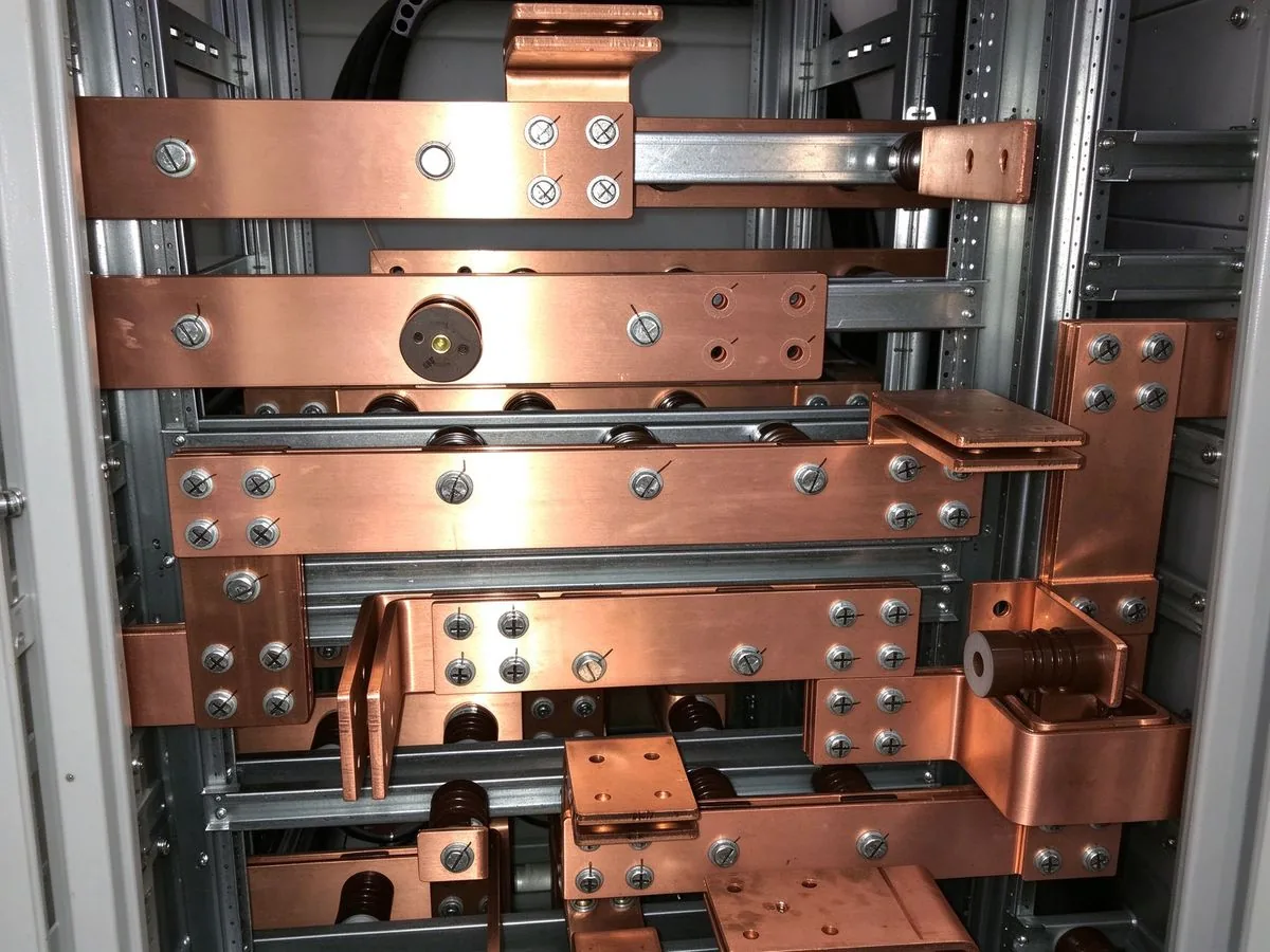
Standard power transformers average about 128 weeks to delivery and generator step-up unit
Read article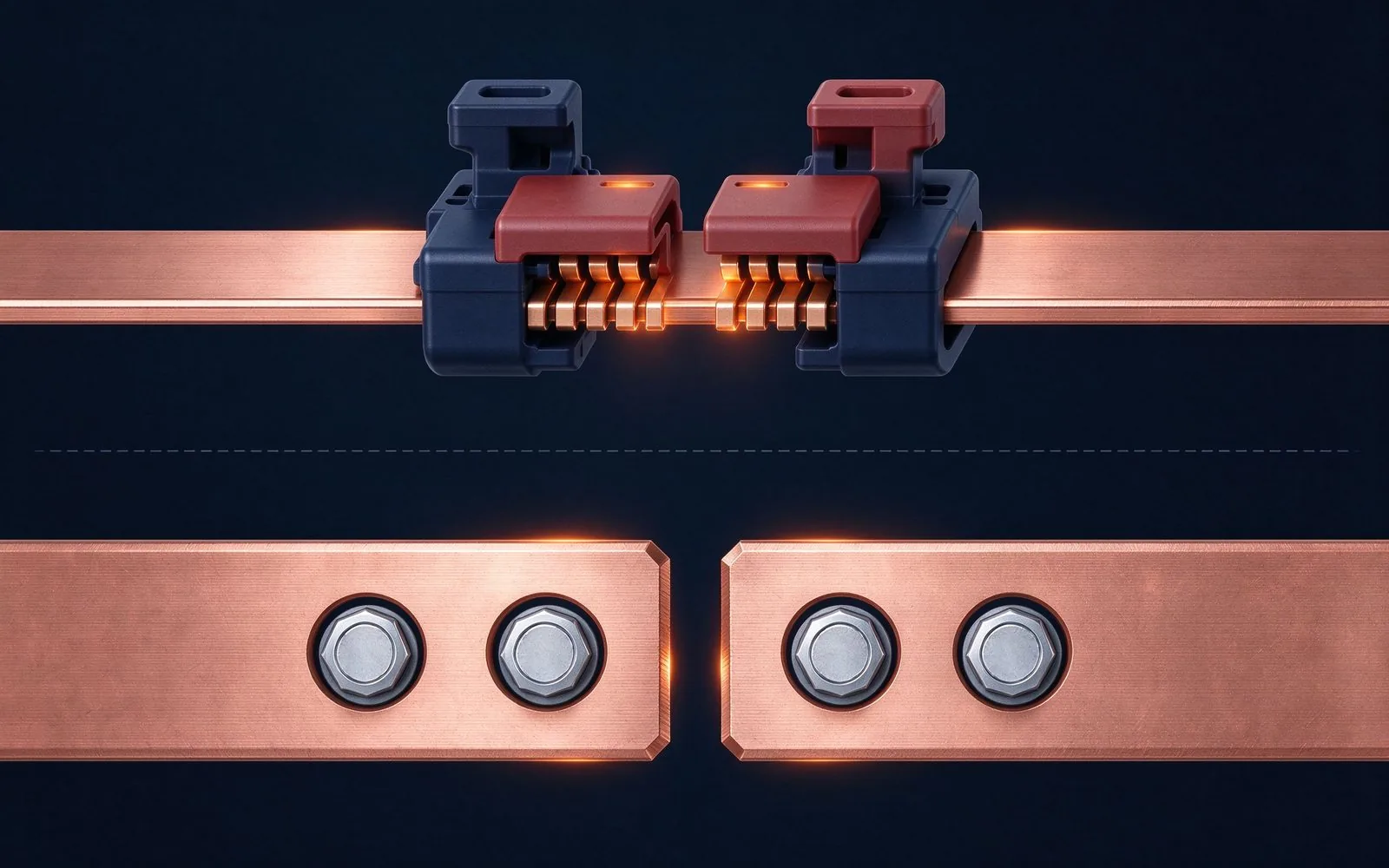
Every busbar selection is really a bet against a failure mode. This guide maps the six way
Read article
Daniel Richter is the chief electrical engineer at SHANYUAN Laminated Busbars, with 15 years in laminated busbar design and current-carrying systems. He leads electrical dimensioning, DC-link layout and thermal simulation for power converters, EV platforms and HVDC stations, and holds an M.Sc. in El
Send the current profile, voltage class and terminal types — our engineers reply within one business day.
