High-current blind-mate connectors exist because a 1,200 A drawer cannot be hand-torqued in a minute. Removing the bolt also removes the certainty: nothing is visible during mating and nothing can be re-tightened in service. This article works through the tolerance stack that decides whether the interface mates, the force and wipe that keep it clean, the 1,000 A thermal budget, the vibration profile behind the fret failure, and the eight values an RFQ must contain.
High-current blind-mate connectors exist because a 1,200 A drawer cannot be hand-torqued in a minute. Removing the bolt also removes the certainty: nothing is visible during mating and nothing can be re-tightened in service. This article works through the tolerance stack that decides whether the interface mates, the force and wipe that keep it clean, the 1,000 A thermal budget, the vibration profile behind the fret failure, and the eight values an RFQ must contain.
A blind-mate busbar connector is a joint that closes without a person looking at it. The plug half is mounted on a drawer, a blade server, a power module, or a battery rack; the receptacle half is mounted on the fixed busbar. When the drawer is pushed home, the two halves engage, and the electrical connection is made by the motion of the drawer rather than by a technician with a wrench.
That single property explains the entire design language around these connectors. Nothing is accessible during mating, so the geometry has to guide itself. Nothing can be inspected afterwards except through a window or a sensor, so the contact has to be robust to partial engagement. And nothing can be re-torqued in service, so the spring force has to hold for a decade.
The applications are specific. Blade servers and AI racks use them because a 1,200 A drawer cannot be hand-cabled in 60 seconds. Battery racks use them because a swap station or a containerised storage unit has to connect a 400 kg module without a torque wrench. Industrial power modules and modular UPS systems use them for the same reason. In each case the connector replaces a bolted joint that was correct electrically but impossible operationally.
That trade is the whole subject of this article: what you give up in contact certainty when you remove the bolt, and how to specify the connector so the loss is managed. The wider comparison of connection types sits in our connector selection guide.
Every blind-mate interface is a stack-up problem. The plug position depends on the drawer rails, the chassis frame, the busbar mounting bracket, and the bar itself. The receptacle position depends on the frame, the bar, and the insulator. Each contributes a tolerance, and the sum has to be smaller than the connector's float.
In a typical rack application the stack looks like this: drawer rail position plus or minus 1.0 mm, chassis frame weldment plus or minus 1.5 mm, busbar bracket plus or minus 0.8 mm, bar flatness 0.5 mm over the contact length, and receptacle mounting plus or minus 0.5 mm. The root-sum-square of those values is around 2.1 mm; the worst-case linear sum is 4.3 mm. A connector with plus or minus 1.5 mm of float passes the statistical case and fails the worst case, which is why good designs are specified against the linear sum rather than the RSS.
The float is usually asymmetric. Axial float, along the mating direction, absorbs depth variation and is typically the largest, 2 to 5 mm. Lateral float, in the plane of the busbar, is smaller because the contacts need alignment to the bar edge, often 0.5 to 1.5 mm. Angular float exists in some designs and is the most expensive to provide.
The practical consequence is that the connector and the busbar have to be designed as one assembly. A customer who buys a connector and mounts it on a bar with a hole pattern from a different drawing has, in effect, built a new interface with unknown float. This is the most common failure we see in first-article submissions.
A blind-mate connector engages in a sequence, and the sequence is a design decision. The first feature to touch is usually a guide pin or ramp that corrects residual lateral offset. Only after lateral alignment does the contact begin to enter the receptacle. Only after the contact is engaged does the power path close.
Guide-first designs protect the contacts from being used as a crowbar. A connector without guide features will mate most of the time, and will occasionally mate with a 2 mm offset that bends a contact finger and creates a high-resistance joint that no one can see.
The guide feature also sets the insertion force profile. A well-designed interface has a force that rises gently during alignment, peaks as the contacts wipe, and then drops as the latch engages. A force that spikes early means the guide is fighting the contacts; a force that never peaks means the contacts are not wiping.
In high-current designs, the guide feature is usually a pair of long pins outside the contact array, sized to carry no current and to absorb the full lateral load of a misaligned drawer. Their length sets the alignment window, and their diameter sets how much misalignment they can correct before they shear.
Insertion force is specified as a maximum for the whole interface, not per contact, and the number matters because a human or a lift mechanism has to produce it. For a rack drawer with a cam handle, 200 to 400 N is a comfortable range. For a battery module pushed by hand, the practical ceiling is lower, around 150 to 250 N, because the operator is usually working at an awkward height.
The force comes from three sources: the spring compliance of the contact fingers times the number of contacts, the friction of the wiping action, and any latch or seal. A 40-contact interface with 5 N per contact is already 200 N before friction.
That is why high-current blind-mate connectors use few, large contacts rather than many small ones. Eight contacts at 20 N is 160 N and carries more current than forty small contacts at 5 N, with far lower variability. It is also why the contact spring material matters: a beryllium copper or high-strength copper alloy spring holds its force after a thousand cycles, while a cheap brass spring relaxes and the force drops by half.
Extraction force is usually specified separately and often higher, because the contact wipe is designed to scrape on the way out as well as in. A connector that is easy to insert and hard to extract is not a defect; it is a deliberate choice to keep the contact clean.
A bolted joint relies on a clean surface prepared by a human. A blind-mate contact relies on the mating motion to clean itself. The contact geometry is designed so that the two surfaces slide 1 to 3 mm while under load, which breaks through oxide films and displaces debris.
Wipe length and wipe force are the two parameters. Too little wipe and the oxide stays; too much and the plating wears through in a few hundred cycles. For tin-plated contacts, a 1.5 to 2.5 mm wipe at moderate force is the usual compromise. For gold-plated contacts, longer wipe is acceptable because gold does not work-harden the way tin does, but gold on a high-current power contact is expensive and usually reserved for signal-level pins in the same housing.
The number of mating cycles is the specification that matters commercially. A rack drawer that is serviced twice a year will see 20 cycles in a decade. A battery swap module might see 3,000. A test fixture might see 50,000. The plating system has to be chosen against the cycle count, not against the current rating.
Tin at 60 cycles is fine for service work and a bad choice for a swap station. This is the point where the connector specification and the plating specification have to be written together, and it is why plating and corrosion behaviour is the companion reading to any connector datasheet.
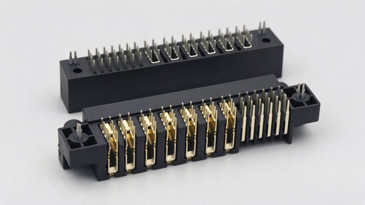
A connector datasheet gives a current rating per contact, usually at a 30 °C temperature rise with all contacts energised, in free air, at a stated ambient. That rating is a laboratory condition, and the field condition is almost never that.
Three derating factors apply. Ambient: a connector inside a sealed rack at 55 °C has 25 K less headroom than the 25 °C test, which cuts the allowable rise roughly in half. Grouping: contacts mounted side by side heat each other, and a 40-contact array can lose 15–25% of its per-contact rating compared with an isolated contact. Airflow: a connector in a still-air enclosure runs hotter than one in a ducted rack, and the difference can be 10 K.
The consequence is that a connector rated at 100 A per contact may be usable at 65 A per contact in the actual installation, and the only reliable way to know is a temperature-rise test on the assembly, not a calculation. This is the same logic that governs bar ampacity, and the ampacity tables apply the same caveat.
Redundancy helps with the electrical problem but not the thermal one. Paralleling four contacts to carry 300 A means each carries 75 A in an ideal world; in reality the contact with the lowest resistance takes more, and the current distribution depends on bar geometry and on how well the contacts are aligned. A 20% imbalance is normal, which is why the array should be specified with margin rather than at the sum of ratings.
At 1,000 A, a blind-mate connector dissipating 30 W is a serious thermal problem inside a sealed rack, and 30 W corresponds to only 30 µΩ across the whole interface. That is a demanding but achievable number: eight contacts at 4 µΩ each in parallel, plus the bar-to-connector interfaces, lands in that range when everything is clean.
The thermal path matters as much as the resistance. Heat generated in a contact has to go somewhere: into the bar, into the housing, or into the air. A connector whose housing is a good thermal conductor and whose contacts are pressed against a copper bar will run cooler than one with identical resistance but an insulating housing that traps heat.
This is why high-current blind-mate designs increasingly use a metal housing, or a plastic housing with a metal heat spreader, and why the mounting surface becomes part of the specification. A connector bolted to a bar with 50 mm of contact length cools differently from one bolted to a 20 mm stub.
In liquid-cooled racks, the connector may be mounted directly on the cold plate, which changes the thermal problem entirely and introduces a condensation risk on the contact surfaces. The cooling architecture is covered in the liquid-cooled data centre busbar article, and the application context in our data centre application page.
One query in our Search Console data deserves attention: high-current busbar connector, blind mating, vibration resistant. It accumulated 79 impressions at an average position of 9.09 over sixteen days, and it produced no clicks at all. That is the signature of a query where the site has a relevant page but no page built specifically to answer it.
The engineering behind the query is real. A rail-mounted or vehicle-mounted busbar joint sees random vibration across a broad spectrum, and a connector that relies on friction alone will fret. Fretting corrodes the contact interface, resistance rises, and the joint fails thermally long before it fails mechanically.
Random vibration is specified as an acceleration spectral density, in g squared per hertz, over a frequency band. Rail equipment is commonly qualified to IEC 61373, which sets profiles for body-mounted, bogie-mounted, and axle-mounted equipment in the 5 to 150 Hz band, with 10 minutes per axis and long-life test durations for the categories concerned. Road vehicle and industrial profiles are set by the customer, but the shape is similar.
Design responses are limited and well known: increase contact normal force so the interface does not separate, add a secondary latch that removes relative motion, use a contact geometry with a wiping action that re-breaks the oxide, or mount the connector on a compliant element that attenuates the input. The bolted-joint version of the same problem is covered in the vibration and bolted joint design article.
A blind-mate connector in a live rack is often mated under load, and that changes everything about the contact sequence. If the power contacts close before the control pins, the inrush current of the load flows through a contact that is still partly engaged, and the resulting arc erodes the plating in a way that a bench test will never show.
The standard solution is a staged sequence: ground first, then precharge through a resistor, then main power, then signal. Each stage uses a contact of different length, so the physical insertion order enforces the electrical order. The precharge contact carries a limited current for a defined time, usually a few hundred milliseconds until the DC link reaches 90% of bus voltage.
Where the load is a capacitive DC link, as in an inverter or a server power supply, the precharge resistor is the difference between a controlled ramp and a welded contact. Where the load is a battery, the direction reverses and the concern is a discharge arc on extraction; the same staging applies, with the main contact breaking last.
The specification item to ask for is the contact sequence drawing, with lengths, and the test evidence that the sequence holds after 1,000 mating cycles. A connector without a documented sequence is not suitable for hot plugging, however good its current rating.
Five tests separate a qualified blind-mate connector from a catalogue drawing.
Mating cycle endurance, to the intended cycle count, with contact resistance measured before, at intervals, and after. The acceptance is usually a millivolt drop limit at rated current, typically 20 to 30 mV per contact pair, which corresponds to a few micro-ohms.
Thermal cycling under load, from ambient to operating temperature and back, at least 100 cycles, with resistance monitored. This catches spring relaxation and differential expansion problems that a static test misses.
Random vibration and shock per the applicable standard, with resistance monitored during the run, because a contact that opens for a millisecond under vibration is a contact that will fail in service.
Salt fog or damp heat, for the plating system, particularly where the housing is not sealed.
And a full-assembly temperature-rise test at rated current in the actual enclosure, because the per-contact rating is a laboratory number.
Our own acceptance sequence for these tests is described in the quality documentation, and the resistance measurement method in the contact resistance guide.
The decision is driven by service access, not by current. A bolted joint carries the most current per unit cost and tolerates the widest manufacturing variation, but it needs a person with a torque wrench and a documented value. A clip-on connector is faster and cheaper than blind mating but needs a hand to release it and reliable guidance to align it. A blind-mate connector costs the most, tolerates the least stack-up variability, and is the only one that works when nobody can reach the joint.
Where the joint is accessible and the assembly is built once, bolted is usually correct. Where the joint is accessible and service is frequent, a clip is usually correct. Where the joint is inaccessible or the module is swapped by a machine, blind mating is the only option and the cost is justified by the downtime it removes.
The second axis is fault current. A bolted joint with adequate bracing survives a fault; a blind-mate connector relies on its housing and latch to hold the contacts together, and its fault withstand has to be tested as an assembly. A connector with a 20 kA rating in a 50 kA system is a fuse with a poor interrupting capability.
The third axis is the bar. Blind mating pushes the tolerance burden onto the bar and its bracket, which is why the bar for these applications is usually a precision-machined part with a flatness callout, not a sheared strip. Our high-current flexible busbar range is specified for these interfaces, and the layer-count trade-offs are in the layer selection guide.
Eight values make a blind-mate RFQ quotable, and eight missing values make it a conversation.
Mating direction and float required, per axis. Insertion and extraction force limits, and whether the actuation is manual, cam, or motorised. Current per contact and total, with the ambient and the enclosure condition. Mating cycles expected over life. Contact sequence, if hot plugging is required. Fault current and duration. Vibration and shock profile with the applicable standard. And the bar interface: material, plating, thickness, flatness, and hole pattern.
Two more items decide whether the project succeeds rather than whether the quote is issued: the first-article acceptance criteria, and the spares strategy. A blind-mate interface with no spare connector kit and a 16-week connector lead time is a single point of failure in a live rack, and buyers who have been through one outage specify spares thereafter.
The same discipline applies when qualifying a second connector source, which is the subject of the dual-source qualification guide, and when translating the interface drawing across languages, covered in the terminology reference.
A bolted busbar joint fails in one of two ways: vibration loosens it or thermal cycling fa
Read article
David Osei is a product marketing engineer covering SHANYUAN's laminated busbar product lines. With 9 years in technical marketing for electrical components, he translates application requirements into product definitions, selection guides and technical content. He holds a B.Eng. in Electrical
Send the current profile, voltage class and terminal types — our engineers reply within one business day.
