Green-hydrogen deployment reached a record 4 GW in 2025, and multi-stack arrays now push kA-level DC feeds from rectifiers into electrolyzer stacks. This piece covers the DC busbar side: sharing, ripple, corrosion, creepage and installation.
Green-hydrogen deployment reached a record 4 GW in 2025, and multi-stack arrays now push kA-level DC feeds from rectifiers into electrolyzer stacks. This piece covers the DC busbar side: sharing, ripple, corrosion, creepage and installation.
This page is an annual rolling data page: the 2026 edition, refreshed once a year as new market data is published.
Electrolysis moved out of the pilot-plant phase and into early commercial volume in 2025. The IEA records global installed water-electrolysis capacity at 2 GW by the end of 2024, with more than 1 GW added on top through July 2025, and a record 4 GW deployed across 2025 against roughly 300 MW five years earlier (IEA Global Hydrogen Review 2025; IEA commentary, 2026). The announced project pipeline toward 2030 still runs to several hundred GW, but the share that has reached a final investment decision stays small: BloombergNEF's 2024 supply outlook tracked about 95 GW in pre-FEED, 35 GW in FEED and only 9 GW at FID.
What this means on the engineering floor is a scale jump. Demo skids of a few hundred kilowatts gave way to 10–200 MW multi-stack arrays, and the conductors between the rectifier and the stacks grew both in per-branch current and in the number of parallel feeders. Most project attention goes to stack efficiency, balance-of-plant skids and wind or PPA matching; the DC copper that carries the rectified current into the cells is often sized late, against a single-line diagram that has not been challenged for sharing, ripple or corrosion.
This article covers the DC side only: the run from the rectifier transformer and rectifier cubicle output to the stack positive and negative terminals. The MV feeder, transformer protection and grid connection are a different study. The related question of electrifying process heat with electric boilers and heat pumps is treated in our industrial-heat electrification piece; here we stay on the hydrogen side — low-voltage, very high-current DC bars, parallel-stack current sharing, ripple and inductance, KOH-mist corrosion, insulation and creepage, hall layout, bar-versus-cable choices, and site installation with thermal movement.
Tracing power from the grid to the cells, the DC busbar occupies the last wet, high-current leg of the chain. A typical low-temperature electrolyzer array looks like this:
Most alkaline and PEM stacks at this power level are unipolar at stack level, with insulation coordinated at the cabinet and skid; bipolar or series-stack arrays do exist, and their insulation class and voltage rating follow a different scheme. The busbar design has to follow the project's electrical single-line, not a generic assumption, because grounding philosophy and touch-voltage rules change with it.
One layout point early: the DC bar sits physically close to the stack head, where electrolyte handling, off-gas piping and occasional spillage are normal. That proximity defines the corrosion and insulation environment discussed later in this article; it cannot be solved by the conductor material alone.
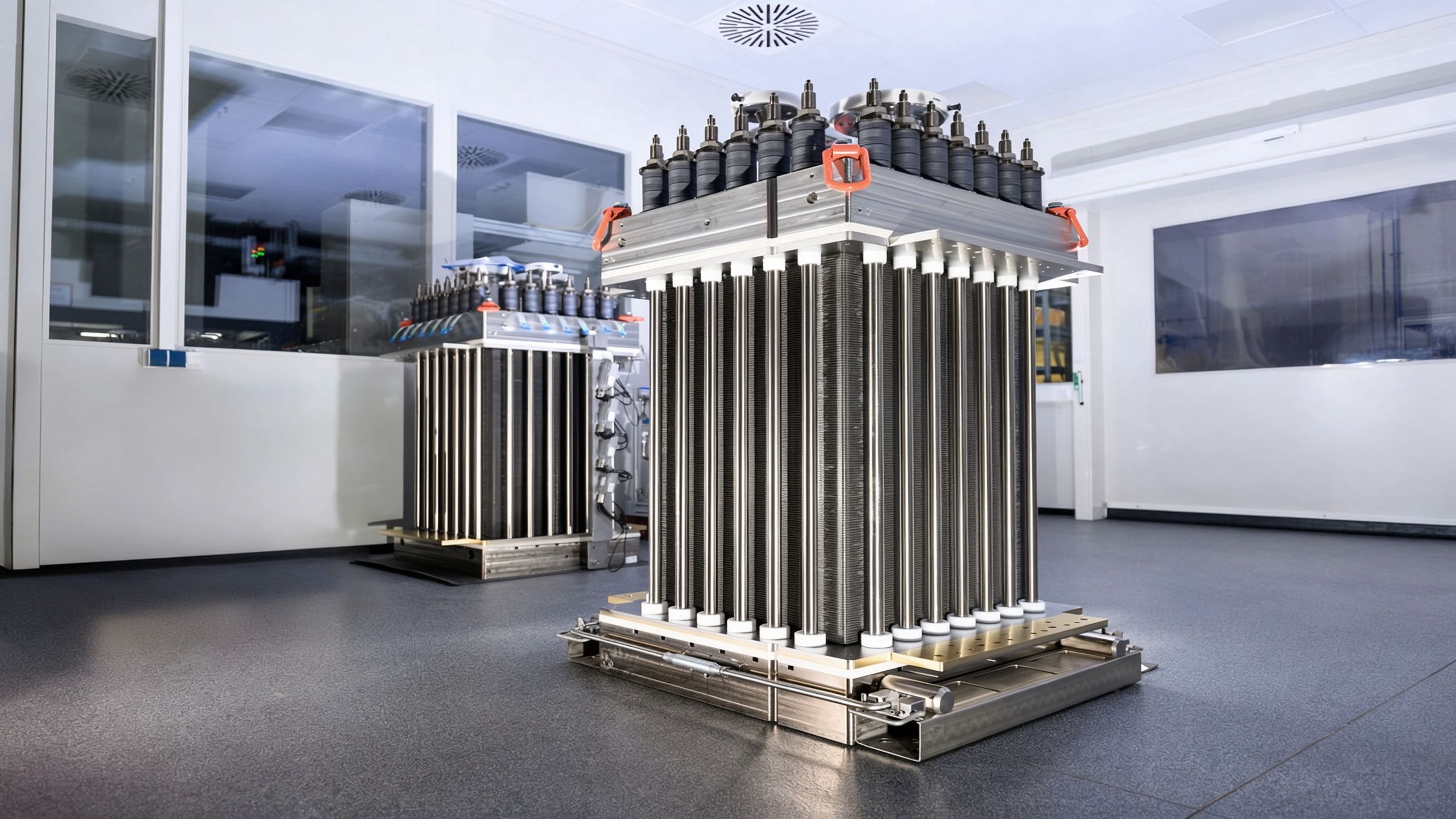
The defining electrical feature of the electrolyzer DC feed is that the stack voltage is low while the power per array is large. Small demonstration stacks run at tens of volts; MW-class alkaline modules sit in roughly the 100–350 V DC class. A published modularization review of large alkaline systems describes a generic stack bus at 335 V DC and 3410 A/m² current density producing 60 kg/h of hydrogen (RSC Sustainable Energy & Fuels, 2024). Power equals voltage times current, so at a fixed power the lower the bus voltage, the higher the current the conductors must carry.
Illustrative arithmetic, to show the scale rather than to size anything: 1 MW at 335 V DC is about 3.0 kA; the same 1 MW at 150 V DC is about 6.7 kA. A 10 MW array split across several stacks therefore does not put a single 10 kA bar in the hall — it puts several branches in the 2–7 kA range in parallel off a common main bus. The actual per-stack voltage and current come from the stack vendor's datasheet and the project one-line; the figures here are order-of-magnitude bands for conductor-class thinking.
Copper cross-section is chosen from steady-state temperature rise, not from a fixed amperage-per-square-millimetre table copied from a switchgear catalogue. Ambient temperature, forced or natural air movement, whether bars are stacked in layers, and nearby heat from the rectifier transformer all move the allowable current. Material choice itself deserves a project-level comparison: copper wins on resistivity, joint stability and fatigue; aluminum wins on weight and raw-material price but brings higher resistance and more demanding bimetal joints. Our copper versus aluminum busbar comparison lays out that trade-off in detail.
The same low-voltage, high-current DC physics appears in another 2026 load: megawatt charging for heavy trucks, port and mining fleets. There the bars land in chargers and high-power cabinets; the rise, sharing and vibration lessons overlap, which is why we cross-reference our piece on the megawatt charging system busbar when comparing conductor classes.
The table below groups common electrolyzer skid sizes into conductor classes. Voltages and currents are illustrative bands derived from published stack and system literature; the final cross-section, layer count and rise margin come from the project's electrical design and the bar's temperature-rise test report. Treat the right-hand column as the environmental starting point, not a finished protection scheme.
| Stack / array capacity | Typical DC bus voltage | DC current (approx.) | Typical conductor construction | Environment countermeasure |
|---|---|---|---|---|
| 0.5–1 MW module | 60–150 V | 4–8 kA per branch | 2–4 parallel copper plates per pole, edge-insulated | Vented stack hall; tin or nickel plating on exposed copper |
| 1–2 MW alkaline stack | 150–300 V | 3–7 kA per stack | Stacked flat copper bars or thin laminate, 1–3 layers | Alkali-mist zone: sealed film plus plating, coated non-contact surfaces |
| 5–10 MW array common bus | 250–350 V | 15–30 kA total, split over feeders | Main bar with parallel shunt sets, symmetric branch drops | Insulated bus duct where wash-down or spillage is possible |
| 20 MW+ hub main DC bus | 300–350 V | 60 kA+ total | Fabricated rigid busbar system with expansion joints | Hall ventilation, floor drainage, corrosion-resistant coating, plated contacts |
Two cautions follow from these bands. First, current per branch — not array total — drives the feeder bar; engineers occasionally size the feeder to the array total and overbuild every branch. Second, the environmental column often forces a heavier or better-protected bar than the electrical current alone would suggest: a 2 kA branch in a dry rectifier room can run bare tin-plated copper, while the same 2 kA branch near the stack head needs sealed insulation and a corrosion-resistant finish.
Arrays above a few megawatts feed several stacks from one common DC bus. Each branch carries what its branch impedance allows: bar resistance from rectifier to stack, terminal and connector contact resistance, flexible-strap resistance, and the stack's own internal voltage-to-current relationship. When the branches are not symmetric, current does not split evenly — the branch with the lowest impedance takes more current, runs hotter, and its resistance rises with temperature, which can worsen the imbalance rather than self-correct. On a multi-stack array this is the most common DC-side fault pattern that shows up only during commissioning, after the bars are already bolted in.
The conductor-level countermeasures are straightforward in principle and easy to miss in layout:
Allowed imbalance between branches is set by the stack manufacturer's specification, not by a general busbar rule; the busbar supplier designs the conductor to keep branch impedance differences small, and the control system monitors the residual. Our dedicated note on busbar current-sharing design works through the impedance matching methods in more detail, including how parallel plates and terminal arrangement affect split.
Rectifier output is not pure DC. A 6-pulse bridge leaves ripple at six times the line frequency; a 12-pulse bridge pushes the amplitude down and moves the ripple to higher frequency. Stack vendors specify ripple voltage and ripple current limits that the DC filter — choke, capacitor bank or both — must meet, and the busbar sits inside that filter loop. Its loop inductance matters because inductance pairs with the smoothing elements to shape the ripple voltage seen at the stack terminals, and because a high inductance in a tight fast-changing current path lets di/dt generate voltage spikes the stack electronics and insulation must withstand.
The standard construction response is to keep the positive and negative poles close together. In a laminated or stacked sandwich bar, the two pole conductors sit separated only by a thin dielectric; opposing currents cancel most of the magnetic field, and the loop inductance drops well below what two spaced flat bars achieve. Layer order, dielectric thickness and terminal geometry all feed that result. The figure below shows the layered pole arrangement used on low-inductance DC bars: conductor, film, conductor, film, with terminals brought out at the same end so the current loop stays short.
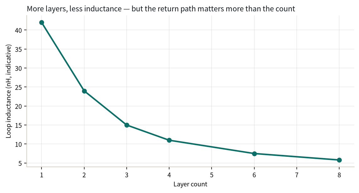
Inductance should be measured, not assumed. Loop inductance on a finished bar can be checked by the impedance or pulse-injection method the integrator's test plan specifies; our guide to loop inductance measurement describes what those measurements capture and where contact styles distort the result. Keep the role of the bar in proportion: the smoothing reactor and filter bank are sized by the system integrator for the stack's ripple limit; the busbar's job is not to compensate for a filter that is undersized, but to add as little stray inductance and loop area as possible.
Alkaline electrolyzers run on a concentrated potassium hydroxide (KOH) electrolyte; PEM systems are acid-side on the stack but still share a wet plant environment. At the cell head, hydrogen and oxygen off-gas carry entrained electrolyte droplets, and venting, seal imperfections and routine sample draws can leave alkali mist and condensate on nearby conductors. The atmosphere around the stack row is damp, alkaline and chemically active, which bare copper does not tolerate indefinitely: copper reacts with alkali and oxygen to form oxide and carbonate patina, contact surfaces rise in resistance, and surface loss eventually threatens the joint.
Conductor protection in this zone is built in layers, chosen to match how exposed each surface really is:
Dissimilar-metal junctions deserve a specific note. Copper-to-aluminum transitions in a corrosive wet environment form a galvanic couple unless made through plated bimetallic clamps or properly sealed transition pieces; bare bolted Cu-Al joints are a recurring failure point in damp plants. Plating thickness, coating adhesion and corrosion acceptance are verified against the project's type-test report and specification rather than a generic claim; our busbar plating and corrosion guide covers finish selection and aging checks in more depth.
The insulation problem in an electrolyzer hall is not high voltage in the conventional sense; it is a wet, contaminated surface problem. Alkali residue deposited on insulation is hygroscopic: it absorbs moisture, forms a weakly conductive film, and that film can carry surface current between poles or from pole to earth. Condensation makes it worse — when a cold bar warms up on start-up, or warm damp hall air hits a cooler surface, droplets collect along edges and insulator ribs. Surface tracking then develops along the insulated face even where the through-air clearance between conductors is comfortable.
Insulation coordination here separates two ideas that engineers often conflate. Clearance is the through-air distance between live parts; creepage is the distance along the insulation surface. In a damp, residue-prone hall, creepage usually governs before clearance does. Practical responses include a larger creepage baseline than a dry switchboard would use, edge-sealed dielectric on film-wrapped bars, ribbed or grooved insulators that break up the surface path, and drainage slopes so water does not pool on horizontal bar tops.
Film choice — PET, Nomex-style aramid paper, epoxy powder or coated wrap — follows the operating temperature, the chemical exposure and the required tracking resistance, and the final insulation system is accepted by dielectric and humidity tests specified in the project standard. Distances and pollution-degree classifications are given by that specification and the type-test report, not by a rule of thumb. Our note on creepage and clearance design walks through how surface paths and pollution conditions are mapped onto insulator geometry.
Busbar design in an electrolyzer array starts as a layout problem. The rectifier line typically sits along one wall, stacks in rows across the hall; the main DC bus runs perpendicular to the stack rows, with branch drops to each unit. That basic arrangement decides how long each feeder is, how symmetric the branches can be, and how close the live copper sits to electrolyte drums, fill points and off-gas piping. Layout changes after the bar is fabricated are expensive, because each branch length and terminal position is cut into the copper.
Maintenance access has to be designed in, not left to floor space that happens to remain. Stack replacement requires lifting the unit out, which means the bar and its supports must clear the removal path; terminal bolts need tool access from the side, and branch bars should be reachable without dismantling the main bus. Working clearance around live DC parts follows the site's electrical safety code, with segregation between positive and negative runs and between the DC bar and AC auxiliaries.
Ventilation does double duty: it carries hydrogen and oxygen away from leak points and keeps mist and condensate from settling on conductors, but it also sets the ambient temperature the bar must be derated against. Where electrolyte storage and fill stations share the hall, the DC bus is routed away from them rather than alongside. Thermal movement between fixed supports is accommodated in the layout by expansion joints or flexible straps near the stack end, so the bar does not push on terminals as it heats and cools through operating cycles.
Conductor choice is not automatically a bar. Cables win where the run is long, the layout is temporary or still changing, or the plant is rented and expected to move; they are also the easier answer when a spare feeder must be kept as a loose reel. But at the kA-per-branch level that electrolyzer stacks draw, cable packs become hard to manage: several heavy parallel cables per pole, large glands and lugs, grouping derating that reduces each cable's ampacity, and the same sharing problem as parallel branches, now multiplied across dozens of conductors.
Rigid or laminated bars win on short, fixed runs inside the hall: high ampacity per unit volume, predictable impedance and sharing, low loop inductance, and a repeatable assembly across identical skids. They also fit arrays built as a fleet of matched stacks, where every branch should look electrically identical. The usual compromise is a hybrid: rigid bar or bus duct runs the fixed main and feeder routes, and a short flexible copper strap or cable tail bridges the last few hundred millimetres to the stack terminal, absorbing misalignment and vibration without loading the stack flange.
Where aluminum conductors are considered for weight or raw-material reasons, the joint and corrosion penalties described earlier apply more heavily in the wet alkali zone; the copper-versus-aluminum comparison remains a project-level decision once current, environment and maintenance philosophy are known. Cable trunking and enclosed bus duct are then chosen for protection where the bar crosses walkways or wash-down zones, rather than as the primary conductor form.
Busbars for an electrolyzer array arrive as pre-assembled sub-arrays: main sections, branch drops, plated terminals and often the flexible straps already fitted. On site, the first checks are incoming-condition checks rather than torque checks: bar straightness, plating and film integrity, terminal cleanliness, and any transit damage to edge seals. Coated or plated surfaces that are scratched in handling should be repaired per the documented finish procedure, not touched up with field paint.
Bolted joints follow a defined torque sequence and a recorded tightening schedule; contact resistance is measured after assembly where the acceptance plan requires it, and insulation resistance and dielectric test are repeated after the bar is installed, because field assembly can introduce a film pinch or a metallic shunt that factory tests did not see. The flexible joint at the stack end is what absorbs the remaining tolerance: stack terminal alignment, frame settling and thermal movement all land on that strap rather than on a rigid bar pushing against the stack flange.
Thermal expansion has to be budgeted between fixed points. Copper expands on the order of 16–17 µm per metre per kelvin; a bar installed at the winter ambient and running hot through summer operation will move several millimetres over a multi-metre run. Expansion joints, sliding supports or flexible sections absorb that movement, and fixed clamps are positioned so they do not lock the bar at both ends. Field cutting, re-drilling or re-plating on site is not treated as an acceptable modification; a changed bar section is fabricated and replaced under the drawing-control process, with the acceptance records updated to match.
We are Rizhao Shanyuan Electronic Components Co., Ltd., based in Wulian, Rizhao, Shandong, manufacturing laminated copper busbars since March 2012 across a roughly 17,200 m² plant and exporting to more than 20 countries. For electrolyzer and green-hydrogen DC feeds, the conductor sub-assemblies leaving our line typically fall into the following groups.
These are conductor sub-assemblies for switchgear and skid builders to install; we do not ship certified rectifier or electrolyzer systems. Heavy rigid DC bar assemblies carry a sample price from US$47–98 on the custom copper busbar product page; series-production pricing is quoted against the approved drawing, and order quantity is agreed per project rather than fixed in advance. Manufacturing controls, plating and insulation verification, and inspection records are described on the quality page.
If your electrolyzer array is at one-line or layout stage, send the stack count, per-stack voltage and current, ambient and mist-zone assumptions, and the branch routing sketch through the contact page; we come back with a proposed cross-section, layer count and rise estimate rather than a generic catalogue rating.
Before a busbar RFQ goes out, the project should have answered the points below. They mirror the sections above; a missing answer here usually means the bar gets sized against assumptions that fail at commissioning.
When the time comes to map a given set of conditions onto a bar construction — current class, layer count, finish and route — our busbar selection decision matrix guide gives the seven-dimension framework for choosing the right construction family, separate from supplier screening and quote comparison.
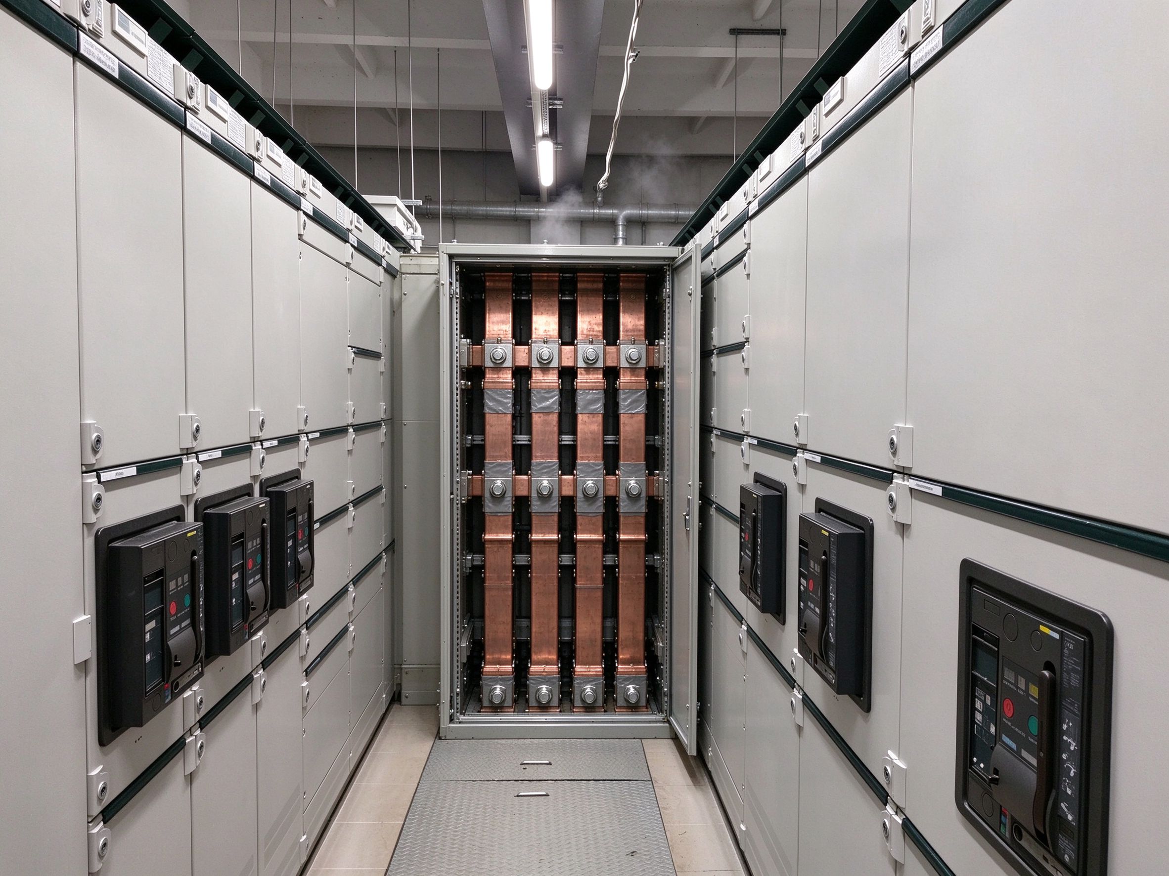
Industrial process heat is moving off gas in 2026, driven by a roughly EUR 64–92/t EU ETS
Read article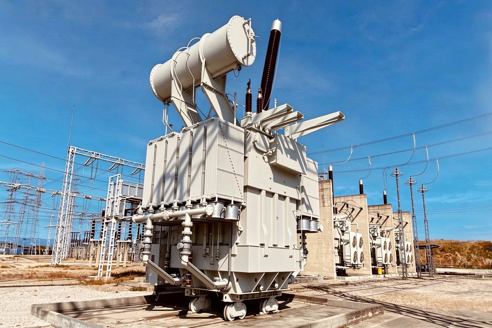
The EU has committed EUR 584 billion to grids by 2030, but busbar orders arrive two to fou
Read article
Wei Chen is a dielectric and insulation specialist at SHANYUAN, with 12 years in insulation systems for laminated busbars. His work covers PET, Nomex and epoxy powder insulation, creepage and clearance design, and partial-discharge-oriented insulation coordination. He holds a Master's degree in
Send the current profile, voltage class and terminal types — our engineers reply within one business day.
