Mon–Fri 9:00–18:00 · CST (UTC+8) · Shandong, China
News · Heavy-Duty EV Charging

MCS 2026: What Megawatt Charging Demands from Heavy-Duty Busbars

In 2026 megawatt-class charging moved from demonstration to early deployment for electric heavy trucks, terminal tractors and mining haul trucks. The busbar in these chargers and vehicles carries 1 MW-class DC current through pulses, vibration and repeated plug-in duty; whether it is the bottleneck depends on where in the power path it sits.

BySHANYUAN Engineering Team Heavy-Duty EV Charging Industry News

In 2026 megawatt-class charging moved from demonstration to early deployment for electric heavy trucks, terminal tractors and mining haul trucks. The busbar in these chargers and vehicles carries 1 MW-class DC current through pulses, vibration and repeated plug-in duty; whether it is the bottleneck depends on where in the power path it sits.

1. Why 2026 is the deployment year for megawatt charging

This page is an annual rolling data page: the 2026 edition, refreshed once a year as new market data is published.

Passenger-car fast charging is largely settled: 350 kW DC stalls, CCS connectors, a familiar cable path. The heavy-duty side is where charging architecture still moves, and 2026 looks like the first year megawatt-class hardware shifted from demonstration fleets toward early deployment. This article covers heavy trucks, terminal tractors and mining haul trucks, not passenger supercharging.

The standards picture firmed up through 2025 and early 2026. CharIN's MCS white paper v2.0 (May 2025) records a 500–1,250 VDC bus range and a maximum continuous current tested to 3,000 A DC, with active cooling recommended for cables, connectors and inlets at higher currents. IEC TS 63379, the connector, inlet and cable-assembly specification for megawatt DC levels, was published in 2026 (CharIN, 2026).

Charger makers are following the standards rather than waiting for every open point to close. Kempower introduced the Mega Satellite Flex dispenser with both CCS and MCS connectors in May 2026 and began deliveries in July 2026 for Europe and North America (Kempower, 2026). The busbar team's question is narrow: where in a 1 MW-class charger does the bar carry the load, and is it the bottleneck, a thermal problem, or a duty-cycle issue?

2. Where megawatt charging actually lands: trucks, terminals, mines

Before sizing any conductor, separate the three duty families MCS-style charging serves. They share the megawatt label but impose different cycles on the hardware, and a spec written for one can be the wrong shape for another.

  • Long-haul and regional trucks. MCS rests on the driver's mandatory break: a partly depleted truck tops up during a short dwell and leaves. Conductors see short, high-current pulses, not steady factory load.
  • Port and intermodal terminal tractors, reach stackers, empty-container handlers. These repeat short yard cycles and charge as opportunity top-up between shifts. Dust, tyre rubber and occasional wash-downs change insulation and sealing more than raw ampacity.
  • Surface mines and large haul trucks. The most demanding end. Charging splits between static high-power DC charging, trolley assist on loaded ramps and battery swapping. CharIN and ICMM published the X-MCS static interface white paper in October 2025 for battery-electric haul trucks; at Oyu Tolgoi, Rio Tinto and SPIC launched a battery-swap haul truck trial fleet that October (Rio Tinto, 2025).

The electrification backdrop moves fast even though trucks remain the slowest road mode. The IEA Global EV Outlook 2026 puts electric trucks at about 9% of global heavy-freight sales in 2025, up from just over 3% in 2024, with battery-electric models at nearly 97% of electric truck sales that year. Vehicle-side context sits in our electric commercial vehicle power distribution overview and the electric haul truck busbar analysis.

A megawatt charging bay under a canopy, with the DC cabinet footprint and cable routing that determine how much copper has to live inside the charger
Figure 2. Charging-bay geometry drives busbar routing and cabinet space. Credit: industrial reference photo (2026), adapted by SHANYUAN.

3. The MCS current envelope: what 1 MW means at the busbar

A common planning mistake is treating "1 MW charging" as one current number. It is not. Current equals power divided by DC bus voltage, and the pack voltage window across a charge is wide: the battery starts at a lower terminal voltage and climbs toward the top of the window as it fills. The same 1 MW pushes more current at the low end of that window than at the high end.

On planning-level arithmetic, 1 MW at an 800 V nominal bus implies roughly 1,250 A, before charger efficiency and conductor drops. At a 500 V lower-window point the same power implies roughly 2,000 A. The CharIN envelope goes further: tested maximum continuous current is 3,000 A DC, and IEC TS 63379 covers up to 1,500 V DC at currents up to 3,000 A for heavy-duty vehicles, buses and off-highway machinery. These are ceiling numbers, not the first-generation operating point; 2026 announcements describe deployments around 1–1.2 MW.

For the busbar this matters twice. Sizing must follow the lowest bus voltage the charger holds while delivering rated power, not the nominal voltage, because that is where current peaks. The path also splits into sections with different duty: the internal DC-link bar may carry continuous converter current, the dispenser feeder carries the charging pulse, and the vehicle-side inlet and its internal bars carry whatever the pack accepts. Each section is sized against its own duty cycle, not the headline megawatt figure.

4. Current density, cross-section and temperature rise

The first instinct in a charger cabinet is to size the bar from current density in amperes per square millimetre. That is a starting point, not the final criterion. DC ampacity is governed by allowable temperature rise above ambient, the heat the exposed surface can convect and radiate away, the temperature class of adjacent insulation and plastic parts, and thermal coupling to components sharing the enclosure.

At DC, skin effect is effectively absent, so current spreads close to uniformly across the section. In a laminated positive/negative/phase stack, loop inductance still depends on layer arrangement and overlap; the interleaving that keeps DC-link inductance low also packs the phases tightly, changing how heat leaves the stack. Contact faces at studs and bolted terminals are where resistance concentrates: a small rise in joint contact resistance converts current to heat where it can damage insulation or relax a bolted connection.

Copper grade, temper and plating follow the same thermal logic. A bare bar oxidizes less in a sealed cabinet but tarnishes at exposed joints; tin plating protects the contact face and is standard at serviceable terminals. Cross-section decisions should be checked against the published ampacity and temperature-rise guidance, then confirmed against the project's thermal test report. No universal safe current-density number survives enclosure changes; a figure quoted without ambient, airflow and insulation class is a planning estimate only.

5. Power levels, currents and typical bar schemes: a planning table

The table below maps common charger classes to an approximate current at an assumed bus voltage, the typical internal busbar scheme, and the paired cooling route. These are planning-level pairings; final cross-sections, clearances and temperature rise come from the project specification and type-test report, not this table.

Charger classAssumed DC busApprox. continuous currentTypical internal busbar schemeTypical cooling route
350 kW CCS dispenser750 V nominal~470 ASingle or dual-layer copper bar with bolted studsAir-cooled, natural or forced ventilation
500 kW high-power dispenser800 V nominal~625 ATwo-layer laminated bar, insulated phase separationForced air; sealed cabinets add internal airflow design
1 MW MCS-class charger800 V nominal~1,250 AMulti-layer laminated DC-link bar with interleaved phases, heavy terminal stackLiquid-cooled terminals/connector path; internal bar often forced-air
1.25 MW heavy dispenser800 V nominal~1,560 ALaminated stack plus copper-alloy terminal region, segmented for serviceLiquid cooling on the high-current path; air-cooled secondary feeds
3 MW MCS envelope ceiling1,000–1,250 V, 3,000 AUp to 3,000 A DCHeavy sectional bar or busway with reinforced support, active-cooled connectorActive liquid cooling required on cable, connector and inlet path

Two caveats sit under every row. Current estimates ignore converter efficiency, conductor drop and charging derating near full state of charge. The cooling split between internal bar and external cable rarely matches: the external MCS cable and inlet are actively cooled because they are flexible and exposed, while the rigid internal bar may stay air-cooled if surface area and airflow suffice. Thermal management of high-current assemblies should be treated as a system exercise across both halves.

6. Terminal and contactor thermal coupling

In a high-power charger cabinet, no component heats in isolation. The busbar, main contactor, fuse block, pre-charge resistor and output terminal bolt onto a shared structure or sit close enough that their warm air plumes meet. A contactor running warm under load raises the local ambient for the bar beside it; a high-current bar radiates heat back onto the terminal stack; a bolted joint with elevated contact resistance becomes the local hotspot pulling both neighbors up with it.

This coupling shows up in field diagnosis as a temperature pattern that does not match the electrical schematic. A terminal reads hot, and the temptation is to enlarge the bar under it, but the real heat source may be the contactor on the same rail whose internal contact resistance has drifted. Spacing, thermal breaks and heat shields are layout decisions as much as conductor decisions.

Joint design at these currents deserves its own discipline. Stud grade, washer type, torque sequence and re-torque policy all affect contact resistance over time, and vibration after transport can loosen a joint that passed factory torque. The separate guide on terminal connection practice covers the bolted details in depth; for MCS design, the thermal model must include the joint as a series resistance rather than treating the bar as a uniform resistor.

7. Liquid-cooled versus air-cooled busbar routes

The liquid-versus-air choice splits by location along the power path. The flexible cable and connector head outside the charger almost always need active cooling at 1 MW and above: limited surface area, repeated bending, and CharIN's active-cooling recommendation for cables, connectors and inlets. The rigid internal bar has more options.

Air-cooled internal bar keeps the cabinet simple: no coolant loop to leak, no pump to service, and the bar can be removed or replaced without draining a circuit. The price is volume — enough surface area and a reliable airflow path, sealing against dust and wash-downs where the site demands it, and fans that add their own failure mode and acoustic load.

Liquid-cooled internal bar buys thermal headroom in a smaller footprint, useful where dispenser volume is constrained or the charger runs repeated back-to-back sessions. It introduces a secondary system: coolant choice (water-glycol versus dielectric fluid near live parts), leak detection, hose routing, freeze protection in cold climates, and a loop service schedule. Whether that complexity pays off depends on duty cycle: a corridor charger pulsing per break and then idling may shed average heat with air, while a depot dispenser on near-continuous high-current sessions is more likely to justify internal liquid cooling.

Public information does not yet support a blanket rule that every 1 MW charger must liquid-cool its internal busbars. The call depends on enclosure size, ambient range, duty cycle, dust and wash-down exposure, and site staffing; that trade-off belongs in the charger specification, not the busbar quotation.

8. Busbar versus high-voltage cable: where the boundary sits

Teams revisit at every charger program where to stop using rigid busbar and switch to flexible high-voltage cable. The two conductors solve different problems, and the boundary follows mechanical function more than current rating.

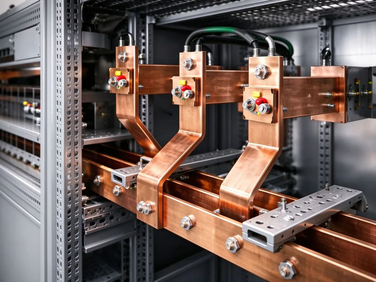
Busbar earns its place where the connection is fixed, the path short, low loop inductance matters, and the joint must repeat reliably across hundreds of units: DC-link between converter and capacitor stack, main feeder to the contactor row, distribution to parallel output stages. A laminated bar also acts as mechanical structure, locating modules and holding terminals at a fixed pitch.

Cable earns its place where movement or separation exists: between a power stage on one drawer and the main bar on the next, between cabinet and dispenser head, where tolerances must be absorbed, or where a module withdraws for service. A flexible conductor absorbs relative movement and tolerance a rigid bar would otherwise match with brackets and clearance, and routes around obstructions in a crowded enclosure.

The practical boundary in an MCS charger tends to be: laminated bars inside the power-electronics block, flexible links across drawer interfaces, HV cables out to the dispenser and vehicle connector. The design risk sits at the transition — a bar bolted to a cable lug, where contact resistance, vibration relief and strain relief must be handled together. Custom copper busbar design for these assemblies should specify the transition joints, not just the straight bar sections.

9. Blind-mate connectors, alignment tolerance and insertion cycles

Automated and semi-automated charging in yards and depots raises blind mating: the vehicle backs under the dispenser head, or the automated connector approaches the inlet, without a human lining up every pin. MCS connector and inlet designs rely on guide funnels, floating contacts and toleranced housings to absorb horizontal and vertical offset as the heads come together.

How much offset a given connector accepts is set by the manufacturer's datasheet and proved in its type tests; it varies between designs, and public information does not support quoting a universal millimetre tolerance for MCS. The right move in a site spec is to take the mating envelope from the selected connector documentation, add the vehicle positioning uncertainty from the yard automation system, and verify the combined stack against the connector's allowable misalignment window.

The busbar behind the inlet has a separate role: it should not carry mating forces. The inlet mounts through its own structure, contact force reacts into the housing, and the internal bar lands on a flexible link or floating terminal so repeated engagement does not work the bar bolt loose or fatigue the lug. Routing a rigid bar directly behind a blind-mate contact, with no compliance in the path, turns every insertion cycle into a mechanical load on the joint. Insertion cycle life and contact wear are connector-level qualifications; the bar's job is to stay out of that load path.

10. Vibration, thermal cycling and plug-in durability

Charger-side and vehicle-side busbars see very different mechanical environments, and a design proved for one should not be assumed for the other. The bar inside a fixed cabinet on a concrete pad sees transport vibration during shipment, then low steady vibration from nearby fans and converters. A bar on a truck chassis or haul truck frame sees road or haul-road vibration, chassis flex and continuous excitation that bolted joints must survive for years.

The failure modes overlap enough to matter. Vibration relaxes bolt preload over time, fretting corrosion can develop at a vibrating contact face, and stud pull-out becomes a structural question when the bar carries bracket loads. Thermal cycling adds a second cycle: the bar heats under load and cools between sessions, expanding and contracting at a different rate from the insulating layer and bolted neighbor, which can loosen a joint or delaminate a bond over repeated cycles.

Our note on vibration and bolted-joint design works through the joint-level countermeasures: lock features, stud sizing, clamping length and torque verification. For MCS hardware, the qualification plan should separate three cycle types — transport and installation vibration, service thermal cycling between charge sessions, and connector insertion life — each with acceptance criteria drawn from the relevant type test or project specification.

11. Maintenance reachability and serviceability in the cabinet

A busbar layout that looks optimal on a current-density spreadsheet can still fail the operations team. Depot and corridor chargers run long hours, and service events — fuse replacement, contactor exchange, a failed power module, insulation repair — are scheduled into tight windows. The bar arrangement determines how fast those events happen.

  • Drawer and module withdrawal. Bars and flexible links must clear the rail travel path; mounting where the module passes forces conductors to be removed first, turning a module swap into a busbar job.
  • Tool access at terminals. Each stud needs socket, wrench and hand space; stacked bars that leave swing angle out of reach are a defect caught only at assembly.
  • Segmentation for replacement. A serviceable bar splits into replaceable sections, not one rigid welded assembly; a local defect should not mean removing the whole feeder.
  • Labeling and segregation. Polarity, phase and torque marked at each joint, live parts segregated from accessible zones, spares matched by drawing revision.

Reachability also shapes the cooling choice. An air-cooled bar leaves the cabinet open to airflow but easier to inspect visually; a liquid-cooled internal route hides heat behind hoses and fittings that need their own inspection points. Neither is wrong, but the maintenance manual has to know which it is. Build traceability — material batch, plating lot, inspection records, revision history — sits under the factory quality and traceability process, and matters more in fleet hardware where a field fix must match the original build.
12. From charger busbar back to the transformer: site distribution

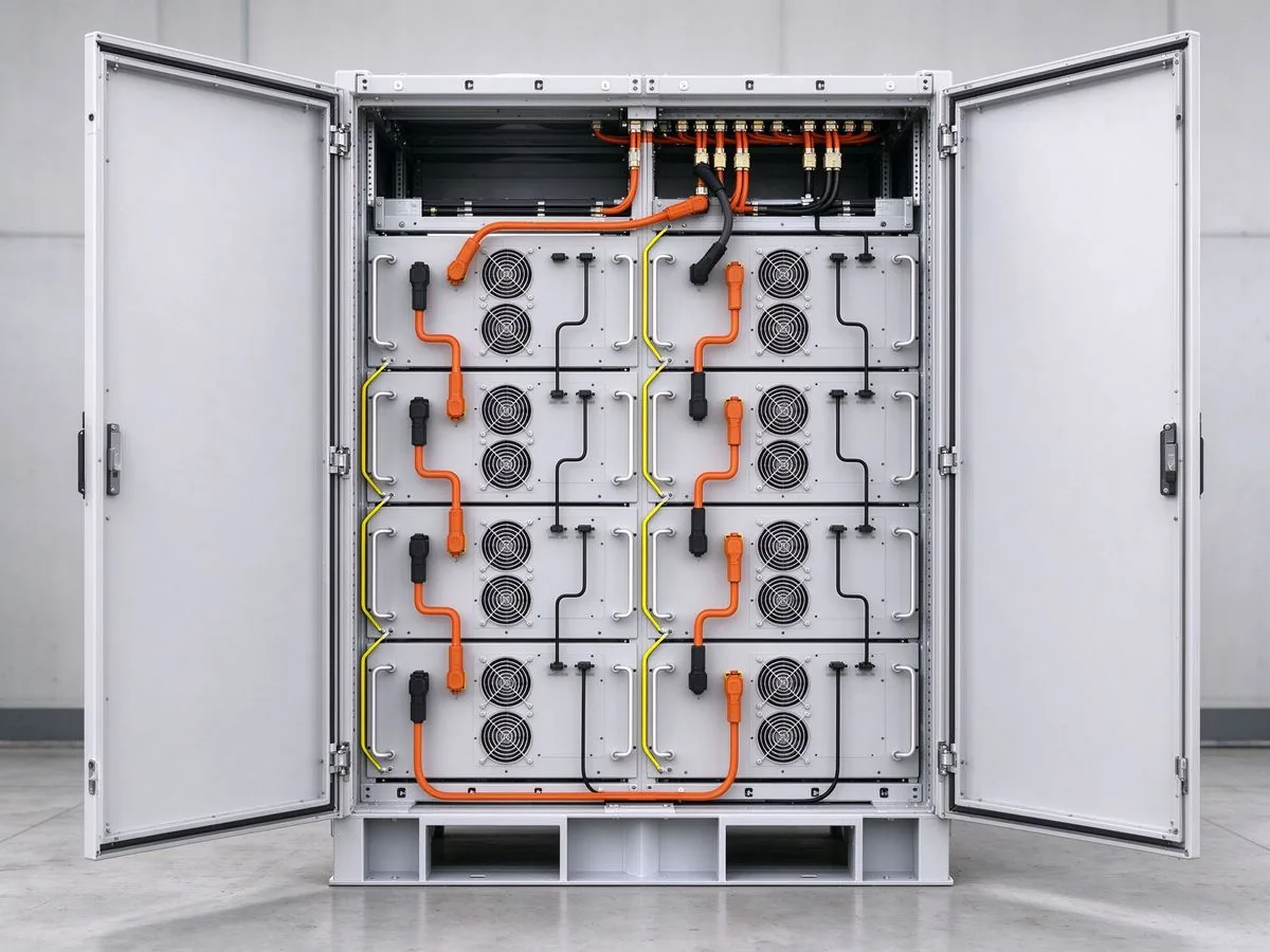
The DC busbar in the charger cabinet is the end of a longer electrical path, and upstream site decisions constrain what the internal bar can do. A 1 MW dispenser does not draw 1 MW from a small feeder; a hub with several dispensers shares a transformer, main switchboard and low-voltage feeders, and the site's contracted capacity, fault level and power-quality allowance determine how chargers can phase their sessions.

Upstream concerns are not direct busbar sizing problems, but they change the duty the bar sees. If the site buffers peak demand with battery storage or grid-forming equipment during charging, the charger DC link may ride through short grid-side dips, and the bar and capacitors then carry transient energy they would not otherwise hold. Harmonic current from converter stages heats bars through losses a pure DC ampacity calculation misses. The feeder fault level sets the prospective short-circuit current bars and contacts must withstand for the protective device's trip duration; let-through energy and magnetic forces are checked against the short-circuit rating.

The planning sequence worth following: confirm transformer capacity and charger count first, then AC feeders and switchgear, then charger internal architecture, and only then bar cross-sections. Specifying a 1 MW-class busbar before the site distribution study risks over-sizing against a duty the site never asks for, or under-sizing against a fault level the feeder can deliver. The same DC baseline appears in our industrial power distribution busbars coverage.

13. Adjacent high-current DC jobs: electrolyzer stacks and BESS acceptance

MCS charging is not the only high-current DC build-out moving in 2026, and engineers comparing notes across projects find shared problems and clear boundaries between them.

Green-hydrogen electrolyzer projects run their own very low-voltage, high-current DC paths from rectifiers to parallel stack banks, with ripple current, current sharing across parallel strings and a corrosive plant atmosphere on the design list. The thermal and contact-resistance fundamentals carry over from charger work; the environmental insulation, creepage and corrosion requirements do not. The dedicated write-up on electrolyzer DC busbar design covers that side of the line.

On stationary storage, grid-scale battery systems are going through a 2026 shift from compliance paperwork to field enforcement and acceptance, with AHJs reading fire-test reports and judging whether damaged DC connections and conductors can be replaced or must be condemned. Charger fleets draw parallel lessons on documentation and residual-damage assessment, though the fire-safety regime itself belongs to storage: see the note on BESS fire code enforcement and acceptance in 2026. Where the three meet is engineering discipline: define the duty cycle, size to temperature rise and fault withstand, document the joint design, and keep traceability through production.

14. A procurement checklist for MCS-stage busbars

For the electrical lead putting a charger fleet or depot program together, the checklist below collects the questions to settle before a busbar drawing is quoted. It is a decision aid, not a substitute for the specification.

  • Duty cycle: peak and sustained current, low-end bus voltage, session duration, back-to-back interval, annual session count.
  • Environment: indoor or exposed dispenser, ambient range, dust and wash-down exposure, humidity, corrosive atmosphere.
  • Cooling route: air, forced air or liquid per path section; coolant-loop supply and service; leak detection.
  • Connection scheme: bolted studs, brazed or welded joints, drawer flexible links, connector mating and cycle-life data.
  • Electrical clearances: clearance and creepage vs working voltage, insulation class, hipot or partial-discharge requirements from the type test.
  • Fault withstand: prospective peak current and let-through energy, coordinated with the protective device trip curve.
  • Mechanical: vibration profile by mounting location, thermal cycling, bracket loads, stud pull-out.
  • Service and traceability: replacement segmentation, labeling, spare-bar revision match, retained inspection records.

On commercial terms, large charger-stage laminated bars sit in the large sample band: a power-electronics laminated busbar lists from US$62 on the product page as a sample reference; production pricing is quoted per drawing once geometry, material and quantity are fixed, and MOQ and discounts are agreed project by project. With a defined architecture and preliminary current duty, the engineering team can turn that into a sized bar scheme and thermal review — reach us through the contact page to start the RFQ. Custom copper busbar programs are developed against customer drawings and test requirements, not a catalog standard.

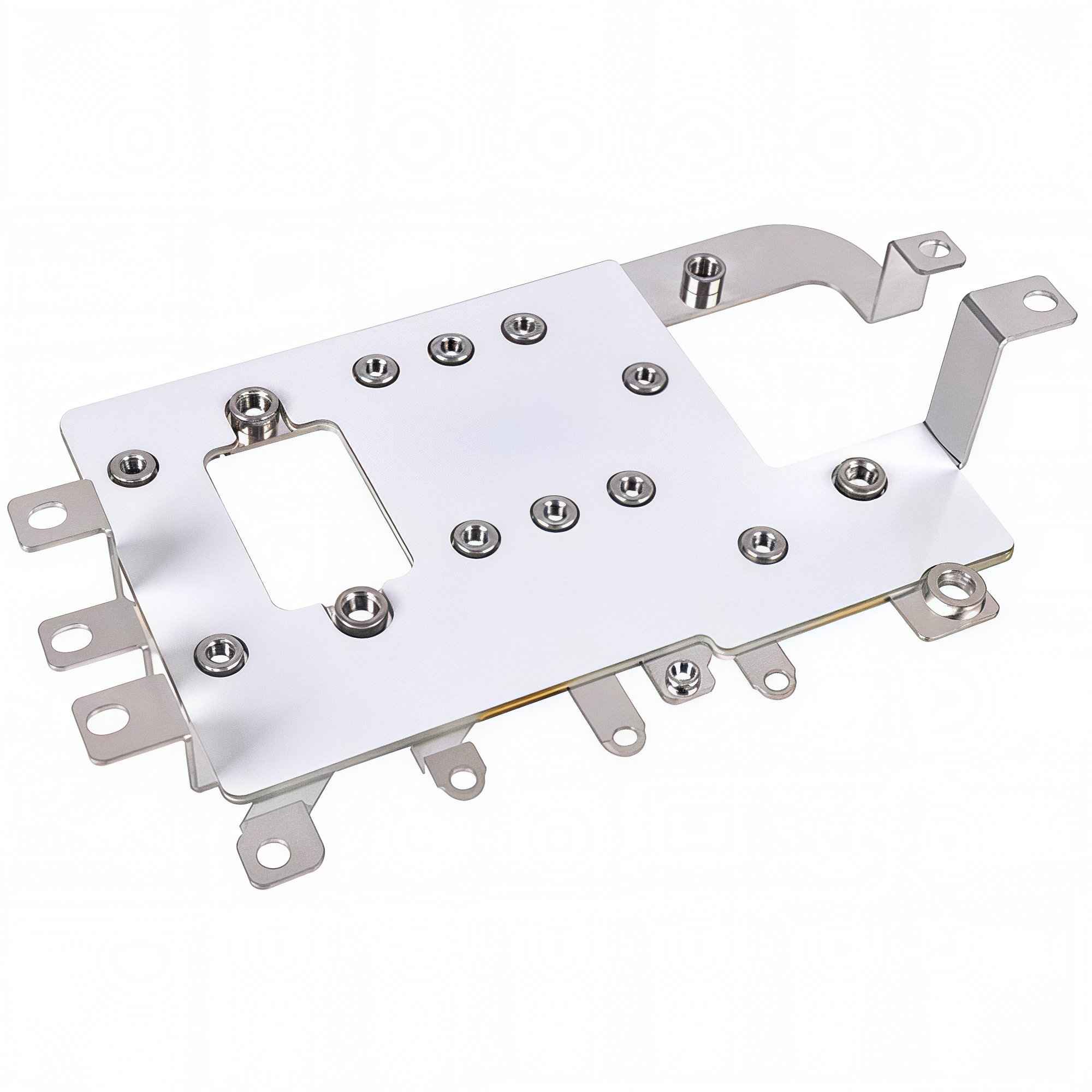
Stamped busbar bracket with pressed studs for a high-current charger assembly

Stamped bracket and stud detail from a high-current charger assembly. Credit: SHANYUAN factory library.

3,000 A DCMaximum continuous MCS current tested to date; active cooling recommended at high currents (CharIN white paper v2.0, 2025).
500–1,250 VDCCharIN recommended MCS bus voltage range; IEC TS 63379 covers up to 1,500 V DC extension (2025–2026).
~9%Electric share of global heavy-freight truck sales in 2025, up from just over 3% in 2024; BEV was ~97% of electric truck sales (IEA, 2026).
>200,000Electric heavy-freight truck sales globally in 2025, tripling year on year (IEA Global Energy Review, 2026).
2026IEC TS 63379 published; first dual CCS+MCS dispensers began deliveries in Europe and North America (Kempower, 2026).
FAQ

Frequently asked questions

Is the busbar the bottleneck in a 1 MW charger?
Usually not the bar itself, but the joint behind it. A properly sized laminated bar carries 1 MW-class current without drama; hotspots most often show up at bolted studs, contactor terminals and transition lugs, where contact resistance concentrates heat. Size to the low-end bus voltage and the thermal test report, then check every joint as a series resistance.
Should an MCS charger use liquid-cooled or air-cooled internal busbars?
The external cable and connector are actively cooled at 1 MW and above; the internal rigid bar has a choice. Air cooling keeps the cabinet simple and serviceable but needs surface area and reliable airflow. Liquid cooling buys headroom in less space, at the cost of a coolant loop, leak detection and maintenance. The call follows duty cycle, enclosure size, ambient range and site staffing; public information does not support a blanket liquid-cooling rule for internal bars.
How much misalignment can a blind-mate MCS connection tolerate?
The allowable offset is set by the connector manufacturer's datasheet and its type tests, and varies between designs. Take the connector's mating envelope, add the vehicle or dispenser positioning uncertainty from the yard automation system, and verify the combined stack stays inside that window. The internal busbar should stay out of the mating-force path, through a floating terminal or flexible link.
Where does busbar stop and high-voltage cable begin inside the charger?
Use rigid busbar for fixed, short, low-inductance paths such as the DC-link and contactor feeder; use cable where there is movement, drawer withdrawal, tolerance absorption or module removal. Mixed assemblies are normal, and the design risk concentrates at the bar-to-cable transition lug, where contact resistance, vibration relief and strain relief must all be handled together.
What should an MCS busbar RFQ specify?
Peak and sustained current at the lowest bus voltage, duty cycle and session count, ambient and contamination class, cooling route by path section, connection scheme, clearances and creepage, fault withstand coordinated with the protective device, vibration and thermal-cycle expectations, and service segmentation with traceability records. Production price is quoted per drawing; sample prices are listed per product family on the site.
Related

Continue reading

Grid-Forming Duty Is a Current Pulse: Busbar Design for Inverter-Led Grids
Energy Storage

Grid-Forming Duty Is a Current Pulse: Busbar Design for Inverter-Led Grids

A grid-following inverter was sized for continuous current. A grid-forming inverter is siz

Read article
800 VDC Comes to the Rack: What It Changes for Busbars
Data Centers

800 VDC Comes to the Rack: What It Changes for Busbars

800 VDC moves the conversion stage to the cluster and pushes a higher-voltage DC bus into

Read article
Lucas Meyer
Lucas MeyerProcurement & Supply-Chain Advisor

Lucas Meyer advises procurement and supply-chain teams on copper sourcing, busbar pricing and supplier evaluation, with 13 years in industrial metals and electrical-component procurement. He developed SHANYUAN's copper-price quotation model and cost-breakdown framework for busbar projects. He h

Copper SourcingProcurement StrategyCost Modeling
See Full Bio

Designing a busbar for this application?

Send the current profile, voltage class and terminal types — our engineers reply within one business day.