A 1 MW AI rack does not fail because the chips are slow. It fails because 48 V cannot carry the current without turning the copper into a heater. The industry answer in 2026 is to distribute 800 VDC into the rack and convert late, which moves a voltage class the busbar has never had to insulate into the space where the busbar sits.
A 1 MW AI rack does not fail because the chips are slow. It fails because 48 V cannot carry the current without turning the copper into a heater. The industry answer in 2026 is to distribute 800 VDC into the rack and convert late, which moves a voltage class the busbar has never had to insulate into the space where the busbar sits.
This page is an annual rolling data page: the 2026 edition, refreshed once a year as new market data is published.
At 48 V, one megawatt of load needs roughly 20,800 A before conversion losses. No practical copper geometry carries that inside a 19-inch rack: the bars alone would consume the volume that the accelerators need, and the I²R loss in the distribution path becomes a cooling problem rather than an electrical one. The arithmetic is unforgiving and it is the reason the architecture discussion moved from cable gauge to voltage class.
Raising the distribution voltage to 800 VDC cuts the current for the same power by a factor of about 16.6. A rack that needed 20,800 A at 48 V needs roughly 1,250 A at 800 V, which is a current range laminated busbars already serve in traction and industrial drives. That is the whole attraction: the connector and busbar industry does not have to invent a new current class, it has to qualify an existing one at a much higher voltage.
The catch is that everything the busbar was allowed to be at 12 V, 48 V or 400 V DC was defined by the low voltage. Clearance, creepage, insulation thickness, cleanliness and touch safety were secondary. At 800 VDC they become the design drivers, and the copper geometry follows them rather than leading.
NVIDIA, Google and Microsoft took the 800 VDC concept to the Open Compute Project and published a joint white paper in March 2026, followed by a low-voltage DC solid-state transformer specification at revision 0.3 in July 2026. The company states that more than 80 equipment manufacturers and infrastructure companies are already building to that specification, which is the clearest signal that this is no longer a laboratory conversation.
The physical layout is a cluster-level power center: AC enters, is converted to 800 VDC centrally, and the DC is distributed to the racks. Inside the rack, a DC-DC stage steps down close to the load, and the number of conversion stages between the grid and the processor falls. Fewer stages mean less conversion loss, and it also means the intermediate DC bus is longer, higher-voltage and more exposed than the 48 V bus it replaces.
NVIDIA's own description of the phased rollout is important for component planning: 800 VDC is introduced where it delivers the most benefit rather than as a forklift replacement. In practice that produces a mixed facility for several years, with 415 V AC, 400 VDC and 48 V rails in adjacent aisles. A busbar supplier that cannot document a voltage class clearly will be asked to supply into that mix, which is where documentation discipline starts to matter as much as copper conductivity.
At 48 V, a busbar is a conductor. At 800 VDC, it is the boundary between a person and a lethal potential, and the enclosure requirements follow from that. Two consequences are easy to underestimate.
First, DC does not cross zero. An AC arc extinguishes at the zero crossing twice per cycle; a DC arc at 800 V sustains until the circuit is physically separated or the available current collapses. That changes the fault-current strategy around the bar: the protection device has to be rated for DC, and the bar has to survive the arc energy long enough for the device to operate. Second, touch safety is no longer satisfied by distance alone. Finger-safe IP2X designs that worked at 48 V need insulating covers, barriers or full insulation at 800 VDC, and the cover becomes part of the qualified assembly rather than an accessory.
This is where the site's existing work on dielectric selection becomes relevant. The material choice is no longer only about withstanding a factory hipot test; it is about tracking resistance, water absorption and long-term surface behaviour in a rack that runs for a decade. A laminated bar with PET insulation that passed at 400 V may still fail a 800 VDC qualification if the surface creepage path is too short for the pollution degree of the room.
The dielectric route is set out in the dielectric selection guide, and the surface behaviour that decides whether a coated bar survives a humid aisle is covered under partial discharge.
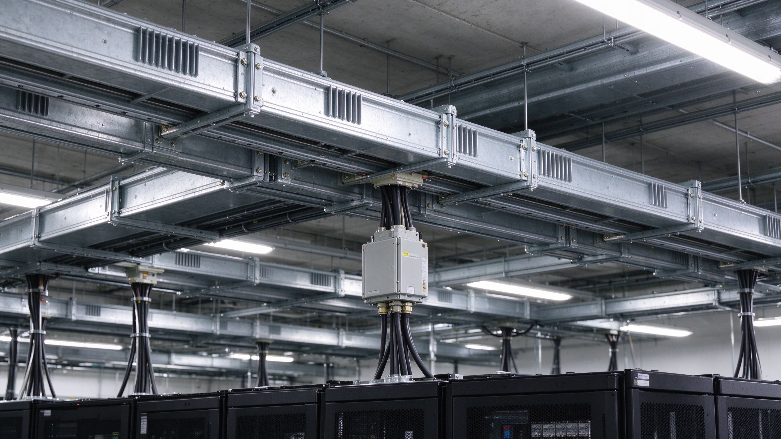
The first calculation every program manager runs is the conductor saving. Going from 48 V to 800 V divides the current by about 16.6, and the naive conclusion is that the copper cross-section falls by the same factor. It does not, for three reasons.
Ampacity is set by allowable temperature rise, not by current alone. A bar sized for a 30 °C rise at 1,250 A in a 40 °C aisle still has a fixed surface area requirement, and the surface area does not scale linearly with cross-section. Second, fault withstand is set by I²t and the temperature the bar may reach during a short circuit, which is independent of the nominal distribution voltage; a 800 VDC bus in a 1 MW rack still has to hold a fault current long enough for a semiconductor or fuse to clear. Third, the mechanical stiffness needed to survive magnetic forces and shipping does not shrink with current.
What actually shrinks is the cable and connector burden, which is the point the OCP work makes: lower current simplifies distribution and reduces the conductor mass in the aisle. The busbar itself stays in the same 500 to 1,500 A family the company already builds for traction and industrial inverters, with the geometry driven by insulation, clearance and fault energy instead of by nominal current.
For the temperature-rise arithmetic behind that number, the ampacity chart and the ampacity calculator are the working references.
The dielectric stack on a laminated busbar carries three jobs at once: separate the layers, hold off the DC potential to the enclosure, and survive the thermal cycles of a rack that switches load many times a day. At 800 VDC the third job becomes harder because the electric field is unidirectional and continuous, which is a different stress from the AC field the same materials see in a drive.
In practice, three material routes dominate. PET film is the cost-effective choice for the internal layer separation where the field is uniform and the bar is fully potted. Nomex adds thermal headroom and mechanical toughness at a price. DLF epoxy coating — the same family the company uses on its standard laminated bars — gives a conformal coating that resists surface tracking and can be specified with a defined dielectric strength per micron. The right answer depends on whether the bar is fully encapsulated or relies on air clearance for the external insulation.
The specification language matters more than the material brand. A drawing that says "PET insulation" tells a fabricator nothing about the number of layers, the overlap at the edge, the void content or the partial-discharge limit. A drawing that states the dielectric withstand voltage, the maximum PD level at 1.2 times operating voltage, the CTI grade and the pollution degree tells the fabricator what to build and tells the test house what to prove.
Layer-by-layer construction and the material trade-offs are described in the power electronics busbar range and the design guide.
800 VDC does not remove heat, it relocates it. The conversion stages that used to sit in the rack move to the cluster power center, so the rack's DC bus carries less loss, but the power center now dissipates the conversion loss in one place. For the busbar, the practical change is that the bar is often the coolest component in an otherwise liquid-cooled rack, and the thermal design has to account for a cold plate on one side and still air on the other.
That asymmetry matters for a laminated stack. A bar with a cold plate bonded to one face runs a temperature gradient through the stack, and the layer nearest the plate is cooler than the layer facing the air. Unequal temperature means unequal resistance, and unequal resistance means the layers do not share current evenly. The usual fix is to derate the assembly rather than to redesign the stack, but the better fix is to specify the thermal interface in the drawing and to test the current sharing under the actual mounting condition.
For air-cooled racks the constraint is the opposite: the aisle is already at 35 to 40 °C and the rack airflow is budgeted for silicon. A 30 °C temperature rise on top of that puts the bar near the limit of its insulation class, which is why the company's standard 30 °C rise rating is a design starting point rather than a guarantee under every installation.
The thermal side of the stack, including current sharing under asymmetric cooling, is treated in thermal management.
The fault current in an 800 VDC rack is supplied by the upstream conversion stage and by any energy stored in the DC link. Two failure modes drive the mechanical design of the bar. The first is magnetic force between parallel conductors, which rises with the square of the current and can permanently deform a stack that was never designed for it. The second is the arc itself: at 800 VDC an arc can sustain for hundreds of milliseconds if the protection coordination is wrong, and the copper that evaporates in that window deposits metal vapour on every insulating surface inside the enclosure.
The design response is not to make the bar heavier everywhere. It is to shorten the unsupported span, to add bracing at the points where the force is highest, and to place the fault current path so that the protection device sees it quickly. A busbar that is mechanically stiff but electrically long will lose the race against a DC arc; a compact, well-braced stack with a fast device in front of it will survive.
This is also the point where the standard work on short-circuit withstand pays for itself. A supplier who can show the I²t the assembly survives, at which duration, and with which protection device, is giving the data center designer something a datasheet current rating never does.
Test-based verification of that withstand is covered in the short-circuit withstand guide.
At 48 V a few milliohms of joint resistance are an efficiency detail. At 800 VDC they are a hot spot in a safety-critical connection, and the failure is not gradual: a joint that runs 20 °C above its neighbours oxidises faster, resistance climbs, and the resulting local heating eventually compromises the insulation around it. The terminal is therefore part of the dielectric system, not just the electrical one.
The site's standard terminal set — M6 and M8 studs, blade terminals and welded tabs — translates to 800 VDC with two changes. Tin plating remains the default for copper because it is stable against oxidation and gives a predictable contact resistance, but the plating thickness and the underlying surface finish become specification items rather than defaults. And the joint has to be torque-controlled and inspectable: a bolted connection that cannot be checked for torque after installation is a connection whose resistance is unknown.
Contact resistance also sets the local field distribution. A void or a lifted film at the terminal end of a laminated bar is exactly where partial discharge starts, because the field concentrates at the edge of the conductor and the insulation is thin. That is why the terminal-end encapsulation on a high-voltage bar is usually the most expensive centimetre of the part.
Stud, blade and welded options with torque windows are listed in terminal machining and the connection reference.
An 800 VDC distribution bus in a rack is not a clean DC link. It carries the ripple of the downstream converters, and the inductance of the path between the capacitor bank and the switching stage sets how much of that ripple turns into voltage deviation. A laminated busbar with a thin dielectric between the positive and return layers is a capacitor in its own right, and the geometry that minimises loop inductance is the same geometry that maximises layer-to-layer capacitance.
The practical rule is unchanged from traction and inverter practice: keep the return layer directly above the outgoing layer, keep the dielectric thin and uniform, and bring the capacitor terminals as close to the switching devices as the layout allows. What changes at 800 V is that the dielectric thickness cannot simply be reduced for inductance, because it also has to hold the DC potential. The designer trades inductance against dielectric stress, and the result is usually a four-layer stack rather than a two-layer one.
The layer count, the resulting inductance and the thermal spread are the three variables the company's existing layer-count method addresses. For a rack bus at 800 V, that method is the right starting point; the difference is that the dielectric thickness now enters the calculation as a constraint rather than a free variable.
The full method sits in low-inductance design and layer-count selection.
A 800 VDC busbar qualification has four parts, and skipping any one of them tends to surface later as a field failure rather than a test failure. The first is dielectric withstand, at the routine test voltage defined for the assembly's rated insulation voltage, applied for the specified duration with the bar in its mounted condition. Testing a bare bar and then installing it against a metal enclosure tests the wrong thing.
The second is partial discharge. A bar that passes a hipot test can still be discharging at a level that erodes the insulation over years. The specification should state the PD limit in picocoulombs at a defined multiple of the operating voltage, and the test should be done at the highest expected operating temperature, because voids that are benign cold can become active hot.
The third is thermal cycling under load, with current sharing measured across the layers at the hot and cold ends of the cycle. The fourth is the mechanical and environmental sequence: torque retention at the terminals, vibration or shipping simulation, and a humidity or condensation exposure that reflects the actual installation. A data center aisle is not a laboratory, and a bar qualified only in laboratory air is qualified for the wrong environment.
Routine and type-test practice is described on the quality page, and the standards behind the test voltages are indexed in the standards hub.
At low voltage, a laminated busbar is a copper part with insulation between the layers. At 800 V, contamination becomes a design variable. Conductive dust, metal burrs left in a drilled hole, fingerprints on a film surface and moisture trapped under a cover all create paths that a hipot test at room humidity will not reveal but a humid rack will.
Three process controls carry most of the risk. Layer registration during lamination determines whether the insulation overlap at the edge is the width the drawing assumed; a two-millimetre shift turns a designed creepage path into a shorter one. Drill and punch quality determines whether a burr bridges the insulation at a hole. And the cleanliness of the assembly before potting or encapsulation determines whether the dielectric interface is solid insulation or a void waiting to discharge.
These are the same controls the company already applies to its traction and industrial stacks, which is an advantage: the 800 VDC data center bar does not need a new factory, it needs the existing process held to a documented tolerance and a traceable record. That record is also what the customer's audit team will ask for when the rack program moves from pilot to volume.
Process tolerances are documented in machining tolerances, and the audit evidence a buyer should request is in the factory audit checklist.
The standards picture is still forming. The OCP low-voltage DC solid-state transformer specification reached revision 0.3 in July 2026, and the joint white paper from NVIDIA, Google and Microsoft set the architectural direction earlier in the year. What does not yet exist in most supply contracts is a single document that tells a busbar fabricator exactly which dielectric, clearance and test regime the customer will accept.
That gap is a procurement risk in both directions. A supplier that waits for a finished standard will be late to the first volume programs. A supplier that assumes its 400 VDC data center experience transfers unchanged will ship bars that pass factory tests and fail site acceptance. The practical middle path is to design to the published architecture, document every assumption, and offer the test data that lets the customer close the gap themselves.
With more than 80 equipment makers building to the specification, the competition is not about who can laminate copper. It is about who can show a qualification file, a traceability record and a change-control process that a hyperscaler's engineering team will accept without a six-month audit cycle.
The neighbouring transition in medium-voltage conversion is covered in solid-state transformer busbars.
When a rack program issues an RFQ for 800 VDC busbars, five items separate a comparable quote from a number that will be renegotiated in the second round. First, the rated insulation voltage and the routine test voltage, stated together with the standard they come from. Second, the partial-discharge limit and the temperature at which it is measured. Third, the fault current and duration the assembly is designed to survive, with the protection device assumed in front of it.
Fourth, the terminal specification: stud size, plating, torque window and the inspection method. Fifth, the documentation package — material certificates, layer registration records, test reports and the change notification process. A quote that omits any of these is not cheaper; it has simply moved the cost to the qualification phase.
For programs still in architecture definition, the useful step is earlier than the RFQ. Send the current profile, the voltage class, the enclosure and the cooling arrangement, and ask for a geometry review before the drawing is frozen. That conversation costs a week and routinely saves a tooling revision, because the insulation and clearance constraints are easier to design in than to retrofit.
For a first geometry review, send the profile through engineering contact; custom stacks are scoped on the custom build page.
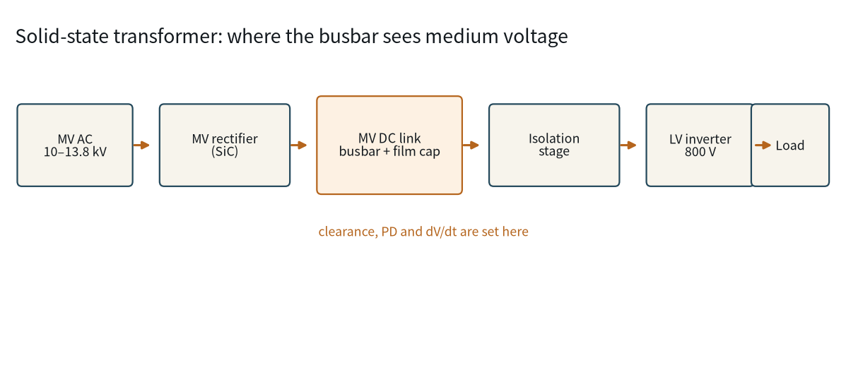
The solid-state transformer replaces a iron-and-copper transformer with a converter stack,
Read article
PET, Nomex and DLF epoxy are the three dielectrics we laminate into SHANYUAN busbars every
Read article
Aiko Tanaka is application engineering manager at SHANYUAN, with 11 years in applying laminated busbars to data centres, energy storage and new-energy systems. She leads application selection, custom-profile development and project delivery, and holds a B.Eng. in Electrical Engineering from the Univ
Send the current profile, voltage class and terminal types — our engineers reply within one business day.
