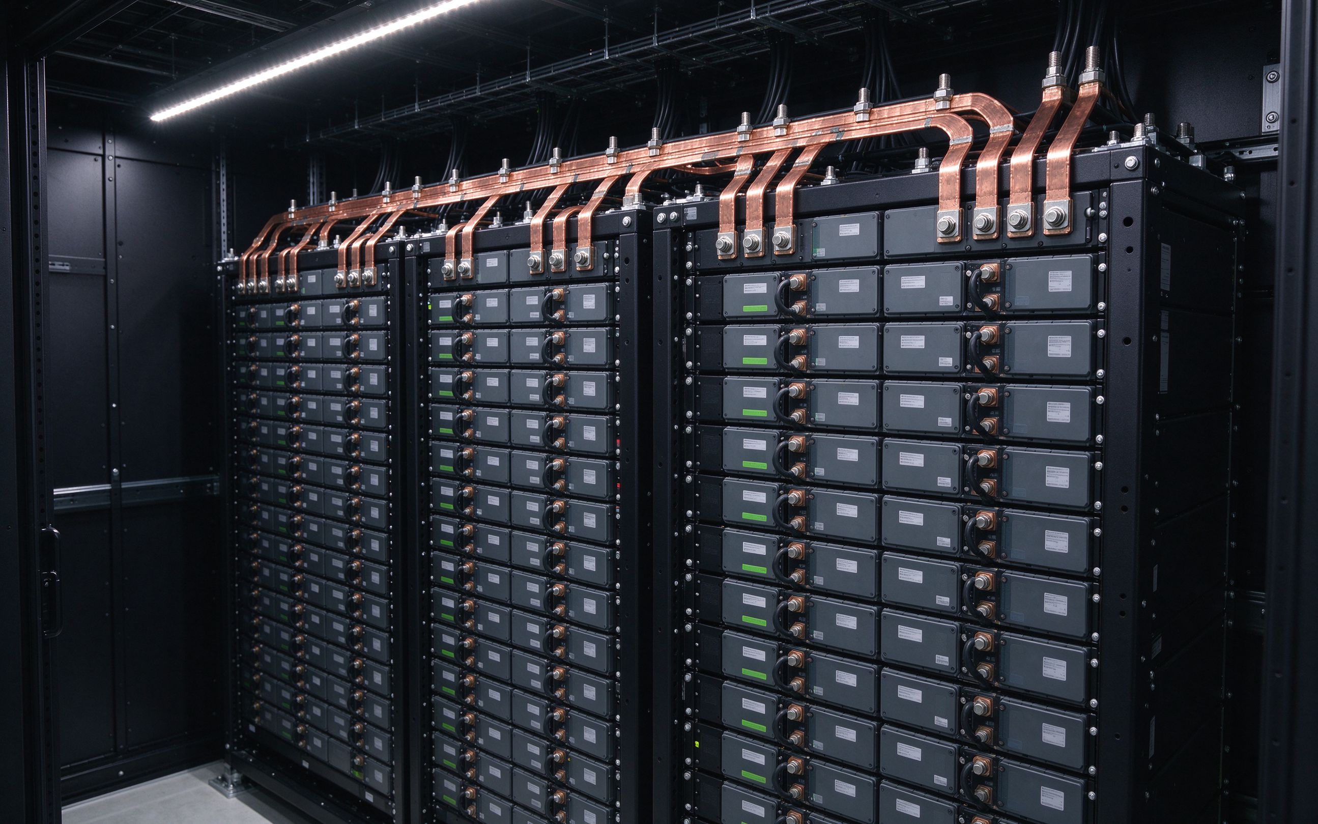
Servers, routers and switches need continuous, low-noise power. We build low-profile data center busbars that distribute DC inside racks with controlled impedance, minimized EMI and hot-swap-friendly service.
The four places busbars carry current in this application.
Low-profile multilayer bars routing the DC supply from the shelf backplane to power modules across server slots.
The laminated DC link between the battery string, the DC bus and the IGBT inverter stage of the UPS.
Compact feeder buswork between the UPS output and the cabinet distribution blocks.
Form-fitting bars inside power shelves feeding multiple power stages with even current sharing.
One-piece laminates carrying power and gate/sense lines where interconnect density is the binding constraint.
Tooled connectors on the busbar enabling plug-in power shelves without shutting down operations.
DC bus voltage and current per rail sets conductor sizing and dielectric choice.
Target impedance or noise budget for the shelf — layer spacing and routing follow from it.
Connector types and blind-mate interface definitions, at quotation.
Height budget and airflow direction — the profile geometry is shaped around both.
Data hall ambient, plus any extended temperature or humidity requirements for edge deployments.
Data centers need continuous power, with retrofits and upgrades that cannot interrupt operations. Preventing thermal and voltage fluctuations is critical for high-performance servers and storage, and telecom/datacom designers must deliver very high interconnect density while minimizing noise and voltage drop — all while supporting hot-swappable boards and subsystems.
Laminated data center busbars become the power-distribution paths inside servers, routers, switches and network cabinets — between the supply and the capacitors, IGBTs or power stages on each shelf. Their multilayer construction brings opposing current fractions extremely close: reference designs hold dielectric spacing under 100 µm between opposing layers, which is what makes the impedance low enough for fast-switching point-of-load regulators. Lower inductance and lower impedance mean less EMI, less RFI, less crosstalk, and tighter voltage regulation at the load.
The UPS that protects the hall uses the same physics on a bigger scale. Modern UPS systems switch IGBT/MOSFET stages at higher frequencies for higher voltage ratings and lower conduction losses; replacing cables with laminated busbars simplifies installation, eliminates incorrect wiring, saves space and increases short-circuit withstand. These UPS busbar designs follow the same inductance-minimization rules as the rest of our power electronics busbars — the loop geometry, not the copper cross-section alone, sets the overshoot at switch-off.
Cost and reliability follow from the one-piece design: fewer parts, no assembly errors, and a structure that also spreads heat. We build 1–6+ layers of C11000 copper, tin-plated and edge-sealed, with tooled terminals matched to your shelf connectors. If you are sizing a distribution bar, start from the reference numbers in our busbar ampacity chart, or send the shelf layout for a DFM review — we reply within one business day.
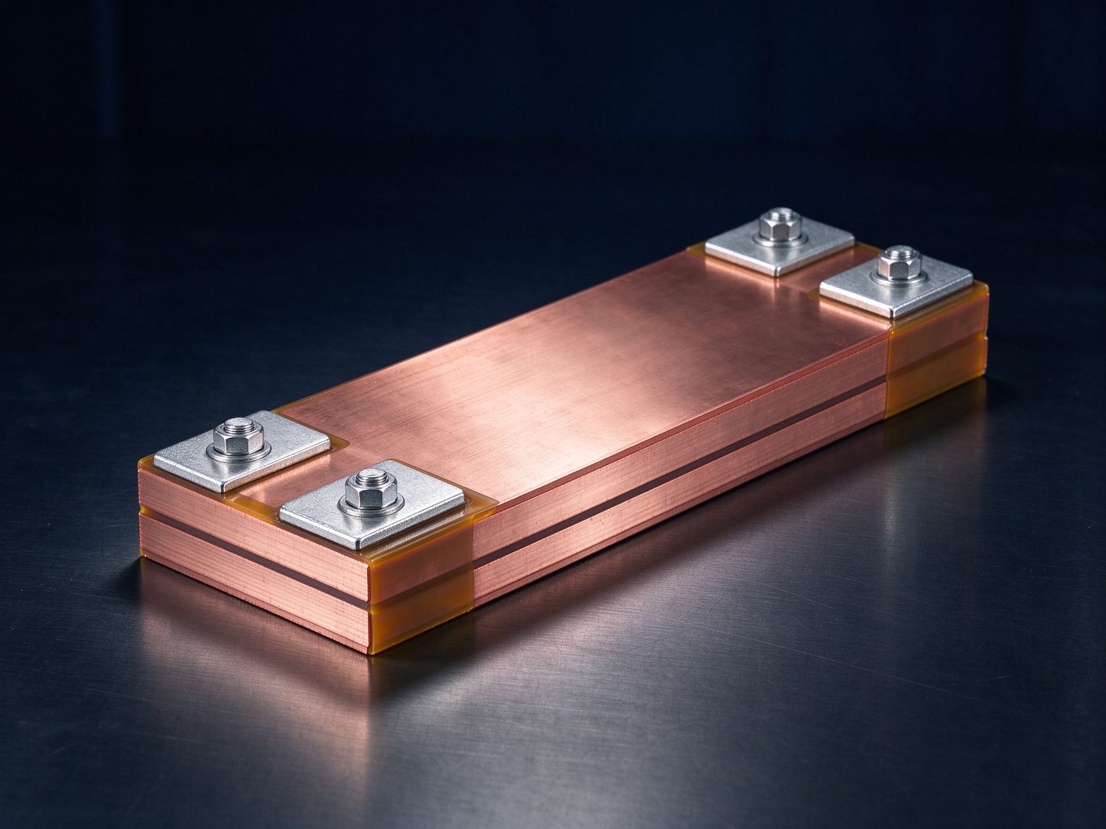
The part this application is built around — a SHANYUAN laminated busbar, factory direct.
Hyperscale racks built on the open rack platform distribute DC power along vertical busbars mounted inside the cabinet, and trays or blades draw power from wherever they sit. The enabling interface is an open-sided, blind-mate connector that clips onto the rack busbar: because the clip has no end stop, it can be positioned at any U-height along the bar, and single-pole clips are used in pairs — one per polarity — to complete the current loop.
Reference ratings for this class of in-rack interface, drawn from industry datasheets: up to 130 A maximum, about 105 A at a 30 °C temperature rise, falling to roughly 85 A when the interface feeds a single 6 AWG cable. The insulation class is typically 600 VAC / 850 VDC, and the connector is load-pluggable — rated for controlled hot-swap interruption at 24 V open circuit — which is what allows trays to be added or pulled without powering down the rack. Insertion force is low, around 12 N typical, and the clip seats through a float-mount insulator that absorbs cabinet misalignment during blind insertion. The mating surface is a nickel-plated copper bar near 3 × 38 mm, terminated to 6 AWG wire; higher-output generations arrive as a two-pole module carrying three 8 AWG high-flex cables per pole.
A second design question inside the rack is noise. Rectifiers switching at the mid-plane inject ringing onto the power path, and cable distribution couples it straight onto sensitive data planes. A multi-layer laminated busbar interleaves ground planes between power conductors; the added inter-plane capacitance shunts switching noise away before it reaches the backplane. The EMI-reduction mechanism is the same plane-coupling principle explained in our low-inductance busbar design article, where forward-return plane overlap is covered in detail.
Reference server-side designs illustrate the rest of the package: blade and receptacle bars insulated with powder coat meeting a 500 VDC dielectric requirement against nearby cabinet metal; floating lead-in contacts that guide blind engagement, with silver plating keeping voltage drop and insertion-cycle wear low; and selected copper sections extruded rather than machined to cut cost. A 43U router build distributed twelve discrete conductors from the laminated bar to mid-plane outputs, with flexible cable tails exiting into floating blind-mate connectors that mate directly to the rectifiers. Where continuous current inside sealed racks climbs, replacing discrete wires with laminated distribution is what holds temperature rise down — sizing guidance for that trade is in the busbar ampacity chart, and the stacked geometry itself is shown under multi-layer insulated busbars.
Reference photographs from SHANYUAN production and shipped assemblies.
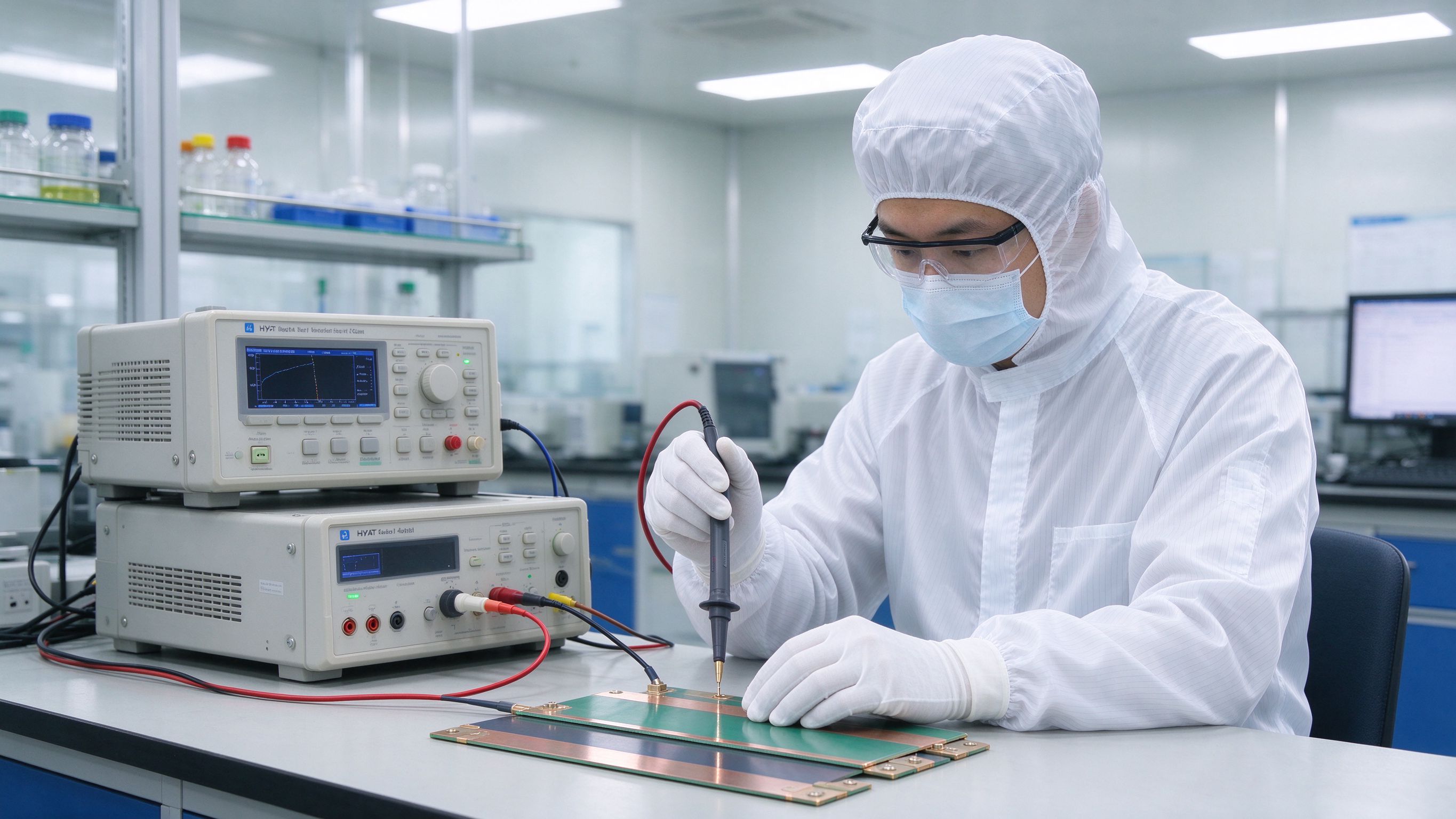
Selected notes and product pages that back the design choices on this page.
From spec review to shipped, tested parts — one accountable supplier.
| Material | Standard options |
|---|---|
| Conductors | C11000 copper as standard; aluminum available on request |
| Dielectrics | PET, Nomex and epoxy (DLF) films, selected by voltage class and operating temperature |
| Plating | Tin finish for corrosion protection and joint solderability |
Voltage class, current profile and terminal types — we will share reference configurations and DFM guidance.
Straight answers from the engineering team.
Send the application, voltage class and current profile — we will share reference configurations and DFM guidance.
Send drawings, current ratings and voltage class — DFM feedback and a quotation within one business day.
