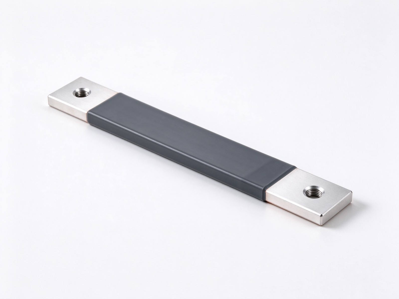
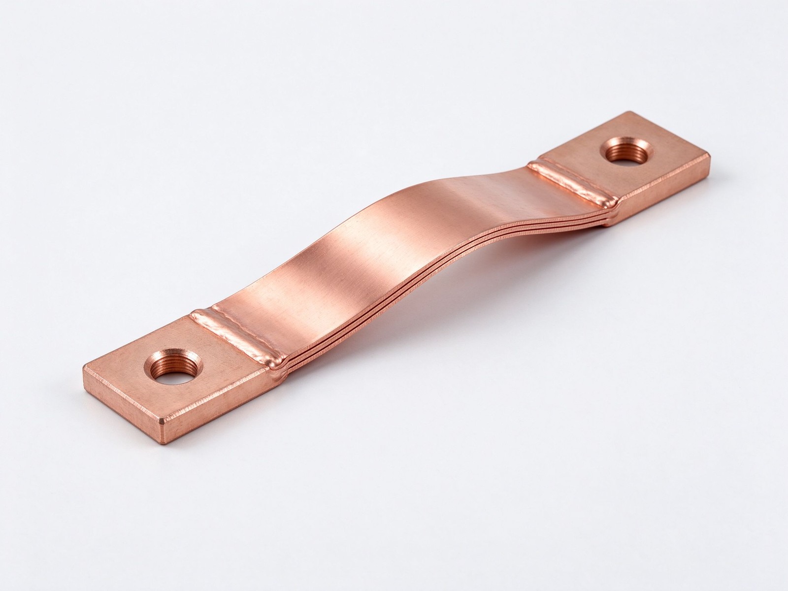
High-current flexible busbar of stacked tinned copper laminates in a PVC jacket, rated 250-2000 A, UL 94 V-0, drill-bolt ends, 100% hi-pot tested - request ampacity data.
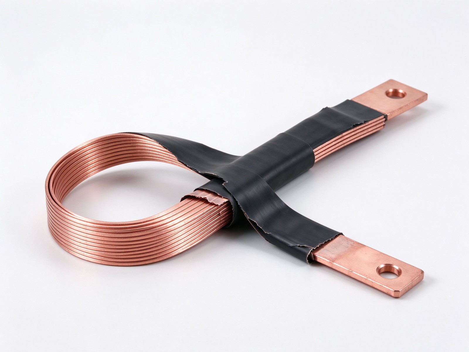
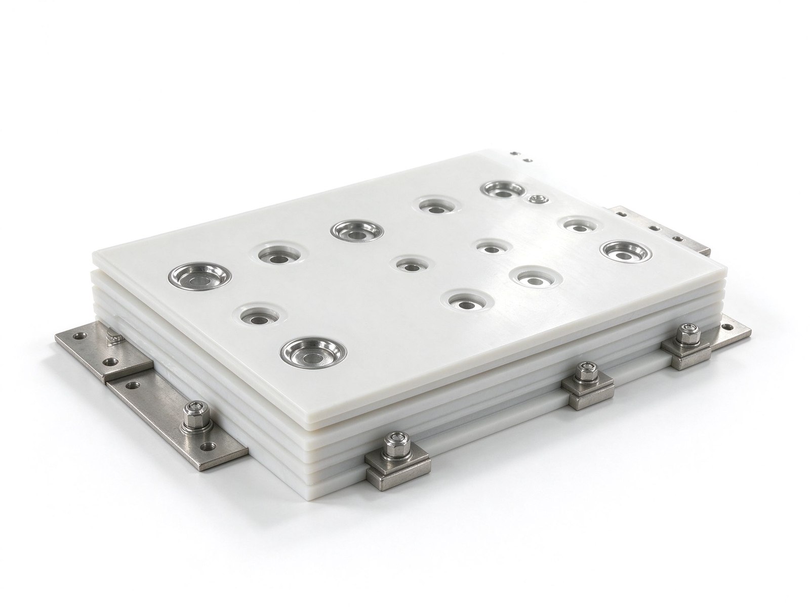
Product imagery: factory photo plus studio renders. The exact geometry, layers and terminals of your part follow your drawing.
Final values follow your drawing — this is the standard configuration of the family.
| Parameter | Value |
|---|---|
| Conductor | Electrolytic tinned copper laminates, 1 mm per layer |
| Jacket insulation | Self-extinguishing PVC, UL 94 V-0 |
| Dielectric strength | 20 kV/mm |
| Jacket elongation / wall | 370% elongation; 0.08 in wall thickness |
| Rated voltage | 1,000 VAC / 1,500 VDC |
| Temperature range | -50 to +105 C; forming range 0 to +55 C |
| Reference standards | IEC 60439-1, IEC 61439-1, UL 67, UL 758, EAC, RoHS |
| SKU | SY-CM-319 |
Key characteristics of this product family.
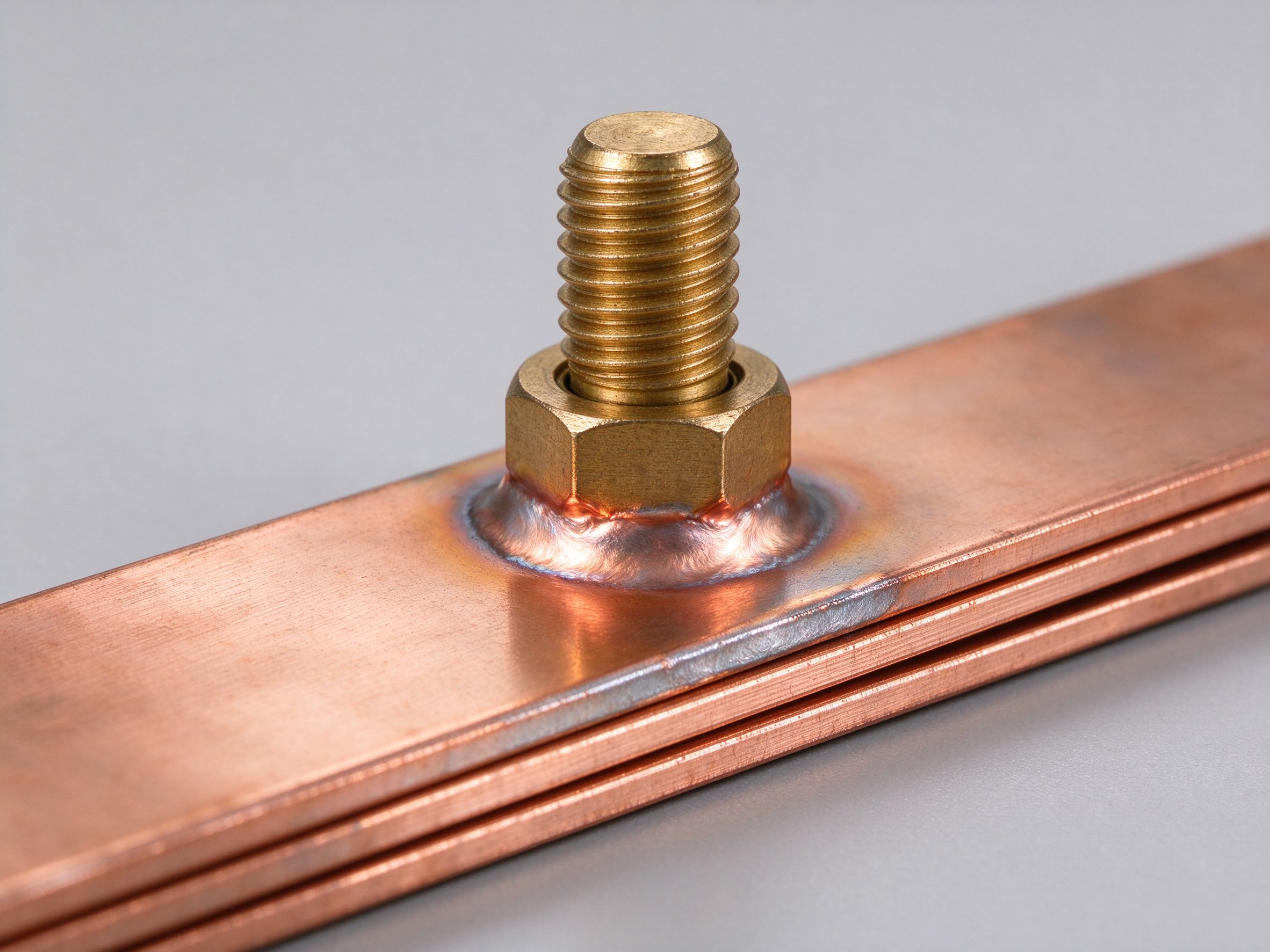
A high-current flexible busbar is a bundle of thin electrolytic tinned-copper laminates, jacketed in a self-extinguishing, high-resistance PVC, that carries 250-2000 A while bending and twisting where an equal-ampacity cable bundle would not fit. The laminated stack gives a far smaller footprint than cable, spreads heat across many thin sheets, and its welded ends bolt directly to equipment - no separate lugs, shorter install time, better vibration behaviour.
The jacket is deliberately sized so the insulation contacts less than 20% of the conductor surface: full contact would lock the laminates rigid and kill the flexibility the design exists for. End connections are drilled and bolted straight through the tinned copper laminates. Every bar is dielectric-tested 100% at production, survives a UL 758 cold-bend test at -40 C, and carries printed traceability codes and part numbers on the jacket for full lot tracking. The range is EAC and RoHS compliant.
Each laminate is 1 mm thick; standard length is 3 m (9.84 ft). Ampacity depends on the permitted temperature rise above ambient: 30, 45 or 60 C. Pick the stack by your rated current and allowed rise.
| Rated current | Layers | Width (in) | Section (kcmil) | 30 C rise (A) | 45 C rise (A) | 60 C rise (A) |
|---|---|---|---|---|---|---|
| 250 A | 2 | 0.787 | 78.9 | 211 | 263 | 307 |
| 250 A | 3 | 0.787 | 118.4 | 263 | 328 | 383 |
| 250 A | 4 | 0.787 | 157.9 | 308 | 385 | 450 |
| 250 A | 2 | 1.260 | 126.3 | 311 | 385 | 454 |
| 400 A | 5 | 0.787 | 197.4 | 351 | 438 | 512 |
| 400 A | 6 | 0.787 | 236.8 | 390 | 487 | 569 |
| 400 A | 6 | 0.945 | 284.2 | 448 | 559 | 653 |
| 400 A | 5 | 1.260 | 315.7 | 507 | 633 | 740 |
| 400 A | 8 | 0.945 | 378.9 | 531 | 663 | 775 |
| 400 A | 10 | 0.945 | 473.7 | 606 | 757 | 885 |
| 600 A | 8 | 1.260 | 505.2 | 657 | 821 | 959 |
| 600 A | 10 | 1.260 | 631.5 | 745 | 931 | 1,088 |
| 600 A | 8 | 1.575 | 631.5 | 786 | 981 | 1,146 |
| 600 A | 10 | 1.575 | 789.4 | 879 | 1,097 | 1,282 |
| 800 A | 5 | 1.969 | 493.4 | 730 | 911 | 1,065 |
| 800 A | 6 | 1.969 | 592.1 | 802 | 1,002 | 1,171 |
| 800 A | 8 | 1.969 | 789.4 | 927 | 1,157 | 1,352 |
| 1,200 A | 4 | 3.150 | 631.5 | 970 | 1,211 | 1,415 |
| 1,200 A | 10 | 1.969 | 986.8 | 1,040 | 1,298 | 1,517 |
| 1,200 A | 6 | 3.150 | 947.3 | 1,172 | 1,463 | 1,709 |
| 2,000 A | 5 | 3.937 | 986.8 | 1,301 | 1,624 | 1,898 |
| 2,000 A | 10 | 3.150 | 1,263.1 | 1,341 | 1,674 | 1,956 |
| 2,000 A | 8 | 3.937 | 1,578.8 | 1,598 | 1,994 | 2,330 |
| 2,000 A | 10 | 3.937 | 1,973.5 | 1,765 | 2,203 | 2,574 |
A flexible busbar only earns its name if the stack can move. The PVC jacket is moulded so it touches under 20% of the copper surface - the rest stays free to slide between layers - which is also how the bar accepts tight site bends without fatigue. Because the ends are bare, drilled and bolted through the laminate stack, no cable lugs appear in the joint, cutting install time and removing the lug as a failure point. Every unit leaves the plant after a 100% hi-pot dielectric test and a UL 758 cold-bend check at -40 C, and the printed jacket code traces the lot. See also our flexible busbar design notes and the wider ampacity reference.
A solid copper bar costs less per amp but fights thermal expansion, vibration and mounting misalignment; a flexible laminated bar absorbs all three, which is why drives, transformer leads and rail equipment specify it. Where flexibility plus PVC insulation is the whole requirement, the adjacent flexible insulated busbar range shares the same laminate construction; where the bar must stay phase-isolated to ground, look at insulated copper busbars. Heat rejection across the thin sheets is covered in thermal management of busbars.
A high current flexible busbar is two material systems at once: the tinned laminate that conducts, and the PVC jacket that holds the stack together without locking it. The report below compiles the typical material figures both systems are quoted from.
| Build Element | Typical Specification | Engineering Note |
|---|---|---|
| Conductor laminate | Electrolytic copper, tinned, 1 mm per sheet | Sheets slide freely inside the jacket |
| Sheet build range | 2 to 12 layers typical | Stack width sets the rated current |
| End termination | Welded solid copper blocks, drilled | No separate lugs in the joint |
| Jacket material | Self-extinguishing PVC | UL 94 V-0 rated jacket, material level |
| Dielectric strength | 20 kV/mm typical | Confirmed by 100% hi-pot before shipment |
| Rated voltage band | 1,000 VAC / 1,500 VDC | Planning value, derated per enclosure |
| Continuous temperature band | -50 to +105 C | Forming range narrower, 0 to +55 C |
| Compliance baseline | RoHS on shipped product | Material-level statement per quality policy |
| Documentation | Lot traceability code on the jacket; CoC on request | Printed per unit |
Compliance wording here stays at the material level: the PVC jacket is self-extinguishing to UL 94 V-0 as a material, and RoHS is baseline on every lot. We do not list a named third-party certification number for the finished bar in this document; request the test and lot records when you need them. The tinned sheets themselves sit at electrolytic copper conductivity, and tinning protects the cut edges from oxide that would otherwise add joint resistance. The welded ends are bulk copper rather than folded sheet, so the bolted joint sees the same contact face it would see on a rigid bar - installers do not change their torque habits. Design context for the laminate build is in flexible busbar design notes.
Specifying the bar on the first pass takes three inputs: the current, the motion and the joint. The table turns each input into the drawing note we need to quote.
| Spec Step | What You Provide | Typical Result We Return |
|---|---|---|
| Current duty | Continuous A plus fault duration | Layer count and width, up to the 2000A flexible busbar build |
| Flexion requirement | Bend radius, bend count, twist | Jacket contact fraction kept under 20% |
| End interface | Studs, holes, bolt torque | Welded block drill pattern |
| Length and offset | Centre-to-centre distance | Fabricated length with install slack |
| Environment | Temperature band, washdowns | Jacket material confirmation |
The stack-and-width answer from step one is only the first pass: inside a tight cubicle the rise band tightens, and parallel runs share heat rather than fresh air. Transformer and switchgear leads usually land near the top of the range; consult the flexible busbar guide for the motion and jacket rules before freezing the drawing. Long runs bend on site only once: the factory pre-sets the main bend plane, and the install absorbs the last few millimetres of offset at the bolted ends. If the duty includes frequent short overloads, budget the layer count from the RMS current rather than the peak: the thin sheets shed heat fast, but the average loss still sets the steady rise.
Where this busbar configuration earns its place.
Where this busbar configuration earns its place.
Where this busbar configuration earns its place.
Where this busbar configuration earns its place.
Where this busbar configuration earns its place.
Where this busbar configuration earns its place.
Your drawings reach the engineers who build the part.
Design risks flagged when changes are cheap.
Test records per lot, CoC and PPAP on request.
Drawing to delivered production parts, one supplier.
From spec review to shipped, tested parts — one accountable supplier.
Straight answers from the engineering team.
Every SHANYUAN busbar is custom, but the power circuits they connect recur across markets. Three typical ones — send us yours and we will point to the right stack-up.
Tight, low-inductance links between the battery source and traction inverters, fully edge-sealed for 400–800 V platforms.
Commutation-loop connections from DC-link capacitors to IGBT bridges, designed against switching overshoot V = L × di/dt.
Converter DC links built for rising bus voltages toward 1500 VDC, with creepage and partial-discharge margins included.
Construction, dielectric selection and current capacity basics.
Read the busbar design guideLayers, terminals, dielectrics and mounting are all configurable. Send us your spec for DFM review and a quotation within one business day.