In October 2026 Tesla announced that Optimus was already on the production line at its Fremont factory, converted from a former Model S/X line in 46 days. In China, industry trackers counted more than 40,000 humanoid robots produced in the first half of 2026 — quarterly growth of 50% — with the Ministry of Industry and Information Technology projecting full-year output above 100,000 units. A humanoid carries 28 to 40 actuators, each with a motor, a drive stage and a controller; at 100,000 units that is 3–4 million servo channels that all need power distributed from a single battery. The DC bus that feeds them — voltage, current, transients, weight — is a genuine power-electronics problem, and laminated busbars are a natural answer. This article walks through the numbers and the engineering.
In October 2026 Tesla announced that Optimus was already on the production line at its Fremont factory, converted from a former Model S/X line in 46 days. In China, industry trackers counted more than 40,000 humanoid robots produced in the first half of 2026 — quarterly growth of 50% — with the Ministry of Industry and Information Technology projecting full-year output above 100,000 units. A humanoid carries 28 to 40 actuators, each with a motor, a drive stage and a controller; at 100,000 units that is 3–4 million servo channels that all need power distributed from a single battery. The DC bus that feeds them — voltage, current, transients, weight — is a genuine power-electronics problem, and laminated busbars are a natural answer. This article walks through the numbers and the engineering.
Three figures frame the market. First, output: Chinese humanoid production exceeded 40,000 units in H1 2026 and the MIIT expects 100,000+ for the full year — a tripling pace. Second, capital: sector financing reached RMB 104.1 billion in the first half, already above the whole of 2025. Third, the benchmark forecast: Goldman Sachs projects a $38 billion humanoid market by 2035 with about 1.4 million annual shipments, while Citi's 2050 projection is $7 trillion and Morgan Stanley's bull case $5 trillion. However you weigh the long-range numbers, the near-term signal is industrial: robots are being ordered in thousands, and each one is a small power-electronics system. The power-electronics busbar content that serves EV inverters applies almost unchanged to a robot torso.
On 21 October 2026 Tesla's Q3 report confirmed Optimus robots were on the production line in Fremont, in a building converted from Model S/X production in 46 days. The detail that matters for suppliers is not the robot itself but the ramp logic: automotive lines are being converted because the manufacturing playbook — tooling, quality gates, supply chain discipline — transfers directly to robot assembly. Automotive-style requirements travel with it: components need PPAP-style documentation, test records per lot, and suppliers who can scale from tens to tens of thousands of units. That is exactly the profile our busbar manufacturer selection guidance addresses, and why robot OEMs are starting to audit busbar suppliers the way EV OEMs do.
A full humanoid body needs 28–40 actuated joints: shoulder, elbow, wrist, hip, knee, ankle, plus the hands, where dexterous grippers add micro-actuators. Each joint is a motor (often a hollow-shaft BLDC or frameless torque motor), a gearbox, an encoder and a drive stage. Semiconductor analysts count roughly 168 power switches per robot at 28 actuators (six per joint for a three-phase bridge); at 100,000 robots a year that is about 17 million switches, and at a million units, 168 million. The drive stage is typically GaN at low power or IGBT/SiC at the high-torque joints, fed from a shared DC bus. The bus has to deliver peak current to several joints simultaneously — walking, lifting and grasping demand simultaneous torque — which is a transient-load problem, not a steady-state one. Low-inductance busbar design is the classic answer to those transients.
Joint actuators span a wide power range inside one robot: fingertip drives pull a few watts through micro-connectors, while hip and knee torque modules can draw 500W to 1kW-plus during a squat or a stair climb. That dynamic range is exactly what makes the DC bus hard to size: the average robot draw may be under 200W of locomotion power, but the peak simultaneous demand across four to six high-torque joints defines the bus cross-section, the battery C-rate and the thermal budget. Designing the bus to the RMS with a headroom factor for transients — rather than to the arithmetic sum of all joint peaks — is the difference between a 1kg copper network and a 400g one. Battery capacity and bus capability are therefore coupled: a lighter bus frees mass for cells, and every gram counts in the same way it does in an EV.
Mobility Foresights estimates the humanoid motor market at roughly $620 million in 2026, reaching $4.85 billion by 2032 — a 40.5% CAGR, among the fastest hardware categories in robotics. Most of that value is in the high-torque joint motors, and every one of them connects to power through a drive and a DC link. For a busbar supplier the read is structural: tens of millions of small power stages, each needing a connection with controlled inductance and verified insulation. The components are smaller than EV traction parts, but the volumes and the vibration duty are harsh — a robot joint flexes millions of cycles. The inverter busbar designs developed for EV programs translate well, scaled down and hardened for cyclic flex.
GaN's switching speed is part of the story. GaN devices switch in tens of nanoseconds, and every nanosecond of switching edge turns loop inductance into voltage overshoot — a 10nH loop with a 100A/50ns edge produces a 20V spike per amp of parasitic inductance squared up the frequency scale. In a robot with a dozen GaN drives sharing one bus, the layout discipline that protects SiC inverters applies at small scale: short, wide bus paths, decoupling near each drive, and minimal loop area from bus to switch to module. Laminated busbars deliver exactly this by construction — the planes are the loop. The low-inductance design guidance for converters is directly reusable, which is why robot power designers increasingly specify laminated busbars rather than wiring between drives.
Humanoid power architectures typically run a 48–100 V battery-to-bus DC link in current designs, with some platforms moving to 200 V+ as power demands climb. Current peaks are the real constraint: a 40-joint robot drawing 100 A steady may pull 300–600 A for a fraction of a second when several joints accelerate together. Those transients land on the bus, and the bus inductance converts them into voltage spikes that stress every drive in the chain. Laminated construction — positive and negative planes separated by a thin dielectric, current flowing in opposite directions — cancels field and drops loop inductance by an order of magnitude compared with wiring. This is the same design principle that keeps SiC inverters alive in EVs, applied to a much smaller, much more flexing package.
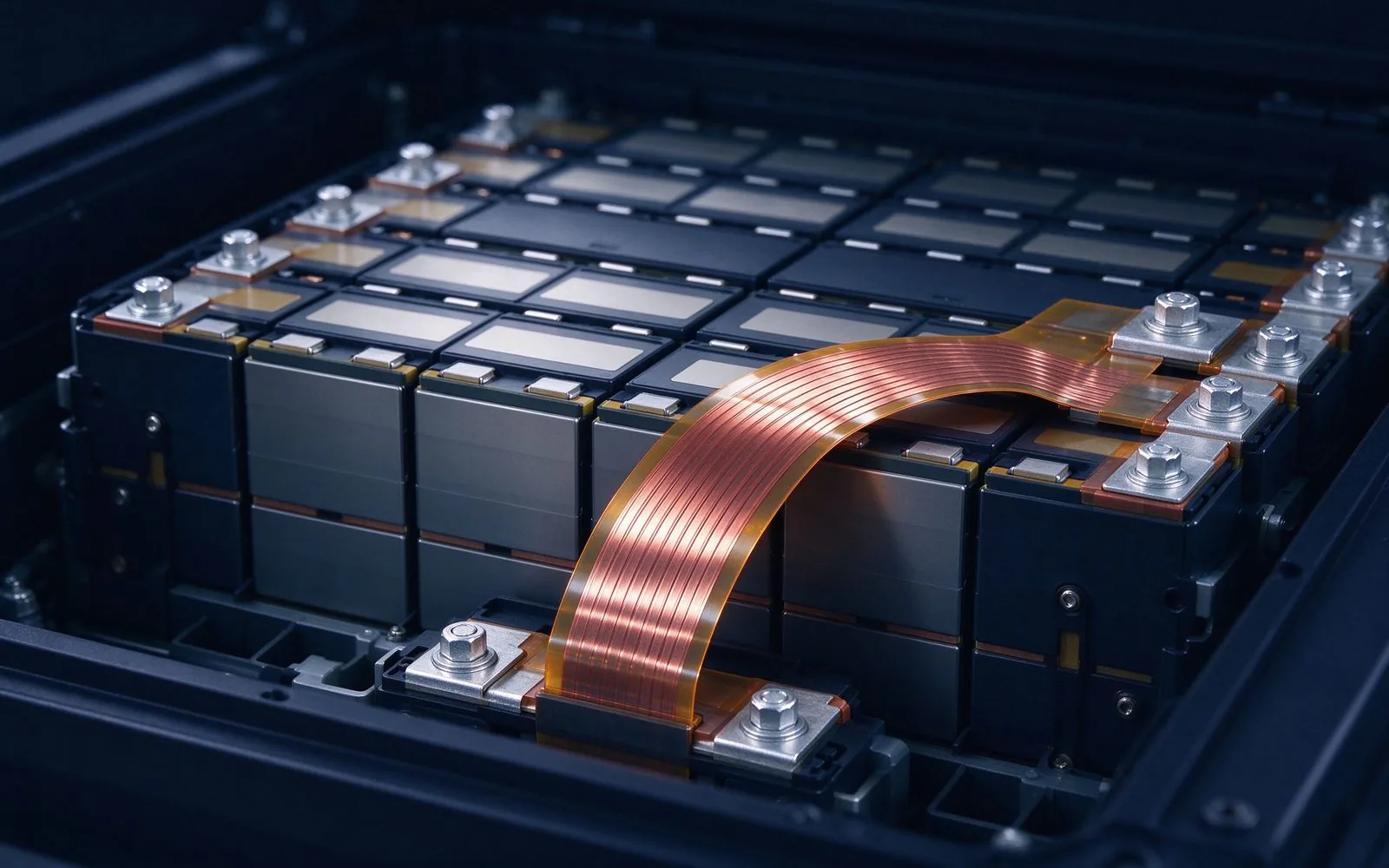
The motor market signal for suppliers is the distribution of sizes: a robot's joint motors range from 20W finger drives to 1kW hip modules, and the busbar content scales with the count, not the size — dozens of small parts, each engineered, tested and traced. That distribution favors suppliers with automated small-part lines and in-line test gates rather than bench-built prototypes, which is why the same automated production economics that transformed EV busbar supply are now reaching robotics.
Three properties make laminated busbars the right fit for servo drives. First, low stray inductance: joint drives switch fast, and fast switching needs a stiff DC link. Second, integrated capacitance: the parallel-plane construction adds distributed capacitance that absorbs switching transients at the point of use, reducing the need for bulky discrete film caps at every joint. Third, thermal coupling: the flat copper planes conduct heat out of the drive stage and into the structure, which matters in a torso with almost no airflow. A robot that operates at 70–85% uptime in factory trials today needs every percentage point of reliability it can get — the quality discipline on these small busbars is exactly what keeps the joints alive through millions of cycles.
The transient story is also a thermal story. A 300–600A spike for 300ms deposits energy in the bus resistance; repeated spikes in a walking cycle raise the steady-state temperature of the torso bus above what a constant-current calculation predicts. Because a robot torso has almost no forced airflow, the bus conductor doubles as the heat spreader, and its thermal coupling to the structure is a design parameter, not an afterthought. Laminated construction helps here twice: the interleaved planes spread current and heat across the full footprint, and the flat surfaces bond to the frame. This is the same logic that drives thermal management in compact converters, scaled to a package the size of a shoebox with actuators pulling watts all around it.
Trace the power chain in a typical humanoid: battery pack in the torso, a master BMS, a main DC bus, then per-joint drive modules. The bus between battery and drives carries the full robot current, and the connections at both ends — battery terminals, bus entry, each drive input — are busbar territory. Flexible copper laminates are particularly useful here because the torso structure moves relative to the limbs: flexible insulated busbars absorb the flex and thermal expansion that rigid bars transmit into solder joints and connectors. The pattern is familiar from battery packs and wind turbines — anywhere conductors cross a moving joint, flexibility is a reliability feature rather than a compromise.
The capacitance argument deserves numbers. A laminated busbar with two 2mm-thick planes and a 0.25mm PET dielectric yields roughly 350pF/cm² of plane area; a 10cm × 15cm torso bus contributes about 5nF of distributed capacitance at the exact point the drives switch. That is not a substitute for a bulk DC-link capacitor, but it is a meaningful high-frequency complement that sits millimeters from every drive input. In a 48V system the effect is modest; at 200V+ platforms it visibly reduces the ringing at each joint drive and the EMI radiated from the torso. The same construction also damps the resonance between the battery cable inductance and the drive input capacitance — the classic low-frequency oscillation that plagues robot power chains built from wiring. These are the quiet reasons laminated construction keeps winning in power-dense, fast-switching hardware.
Every kilogram in a humanoid is a kilogram of actuation performance lost. Copper at 8.9 g/cm³ is heavy, and a full-robot bus network can reach hundreds of grams to a few kilograms of conductor. Where current density permits, aluminum cuts weight by roughly half for the same cross-section — the trade-offs of copper versus aluminum apply directly. The subtlety is in the joints: aluminum needs bimetallic transitions at copper terminals, careful torque control, and plating compatible with its oxide layer. Designers working to a weight budget should allocate the copper where transients are highest and consider aluminum for the steady-state torso bus, using the bimetallic and busbar connection guidance published on this site.
Factory pilots at BMW and Hyundai in 2026 ran humanoids at 70–85% uptime against a 95% target — a gap that suppliers are being asked to close. Downtime in a robot is rarely a single component; it is usually a cascade from a connection that loosened, a joint that overheated, or a sensor that lost its supply. From a busbar standpoint the reliability levers are mechanical: controlled torque, spring washers where vibration is expected, plating that resists fretting, and insulation that survives flex without cracking. The welded busbar assemblies used in high-vibration EV programs remove the bolted joint as a failure mode entirely, and the same logic is migrating into robot joints. Reliability targets like 95% uptime are met at the connection level first.
Robot busbars are smaller than EV traction bars but the test menu is the same: dimensional inspection, continuity, insulation resistance, dielectric withstand, and — for the flexing joints — mechanical and thermal cycling. The volume is the differentiator: hundreds of thousands of units means the test gates have to be in-line and fast, the way factory video verification shows for SHANYUAN's own lines. Partial discharge testing matters on any 200 V+ DC bus with tight clearances; the PD-free design guidance for converters applies to a robot's 300 V bus as much as to a traction inverter. Specifiers should demand per-lot test records at the currents and voltages the robot actually sees, not a generic certificate.
The uptime gap also has a data dimension. A 70–85% robot uptime means roughly 15–30% of scheduled time is lost to faults, and most of those faults are electrical and mechanical connections rather than the motors themselves. The industry response is condition monitoring — sense points on the bus, temperature probes at joints, torque logging on critical bolts — which the busbar design must accommodate by adding test pads and mounting points for sensors. A laminated bus with integrated sense terminals costs little more and turns the torso bus into the robot's electrical nervous system: voltage at each segment, current per drive group, temperature at the hottest joint. The quality infrastructure that supports per-lot records and traceability is the same infrastructure that supports fleet-level monitoring once the robots ship.
Before quoting a robot program, lock down five parameters: (1) the DC bus voltage and its tolerance band; (2) peak and RMS current at the bus, including simultaneous-joint transients; (3) the vibration and flex profile at each connection — cyclic, not just random; (4) the thermal path, since torso airflow is minimal; (5) the assembly method, bolted or welded, and the torque spec. Then choose construction: rigid laminated for the torso backbone, high-current flexible busbars across moving joints, and plated terminals matched to the cell or drive connectors. A complete RFQ data package — drawing, 3D model, duty cycle, dielectric class, plating, terminals, volumes — gets a comparable quote; the sample-to-series path then de-risks the ramp from prototypes to tens of thousands.
For a robot program in the tens-of-thousands range, the qualification sample matters more than the production part: it is where the flex cycling, the torque retention and the withstand margin are proven before the tooling commits. A practical sample matrix is three parts: one part for fit and form, two for thermal cycling, two for flex cycling at the joint profile, and one retained as the audit master with its full test record. The supplier should document the test currents at real bus voltages and the number of flex cycles with the resistance drift per cycle. Per-lot records on serial production then trace back to that qualification baseline — the same audit chain automotive programs use, and the one our quality gates are built around.
Three trends decide where robot busbar demand goes next. First, voltage: platforms are creeping from 48 V toward 100–200 V DC as power demand grows, which raises insulation and PD requirements. Second, volumes: if China hits 100,000 units in 2026 and scales from there, the component supply chain will shift from prototype shops to automotive-style production lines — the same transition EV busbars went through. Third, integration: robot makers will increasingly design the torso bus as one laminated assembly rather than a bundle of connectors, because integration reduces mass and assembly time. The SiC and power-module market analysis on this site and the DC-link busbar deep-dive describe the power-electronics layer this trend builds on.
Standards are still forming, which makes disciplined component selection more valuable, not less. Robot-specific electrical standards are young — general machinery and battery standards cover much of the ground today — so the buyer's own spec becomes the de facto requirement: bus voltage range, dielectric withstand, insulation class, flex cycles, thermal range. A component qualified against a written spec, with per-lot records, transfers cleanly when the industry standard matures; a component bought on a drawing alone does not. This is the same reasoning that pushed EV busbar supply into PPAP-style documentation, and robot programs are following the same curve. Buying ahead of the standard means buying the documentation as well as the part.
How many busbars does a humanoid need? A typical unit uses one torso DC bus assembly plus per-joint drive connections — on the order of 30–40 small busbar parts, some of them flexible. Is robot busbar volume meaningful for suppliers? At 100,000 robots × 30 parts, yes — 3 million+ small assemblies a year at full production, with automotive-style quality requirements. Do robots need welded or bolted connections? Both: welded assemblies dominate where flex and vibration are high; bolted joints remain where service access matters, with controlled torque and locking hardware. What voltage do current humanoids run? Mostly 48–100 V DC today, moving toward 200 V+; PD and insulation requirements follow the voltage, not the application.
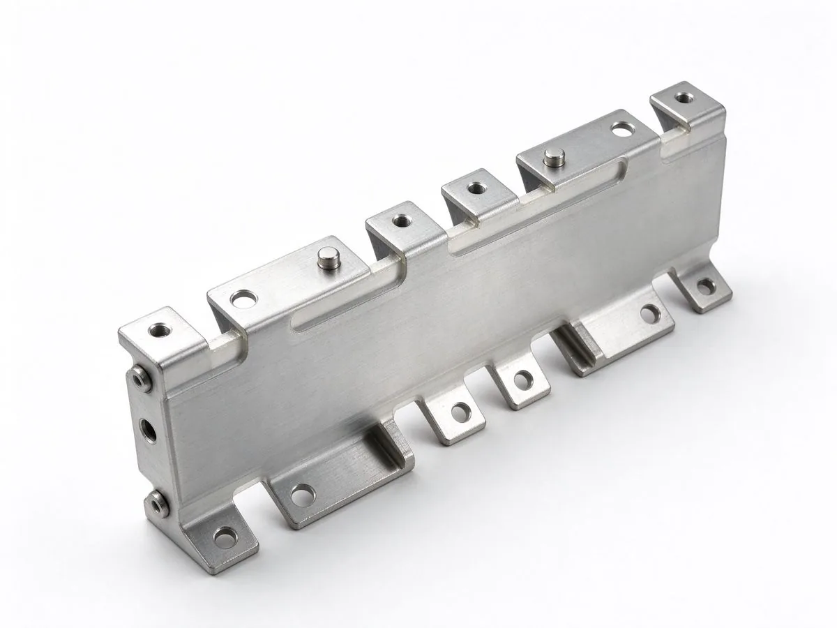
Higher switching speeds from SiC MOSFETs and modern IGBTs are pushing the DC-link busbar t
Read article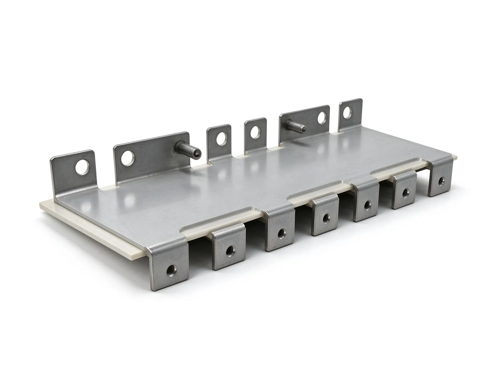
SiC is scaling up — literally. Eight-inch wafer capacity is expanding at double-digit CAGR
Read article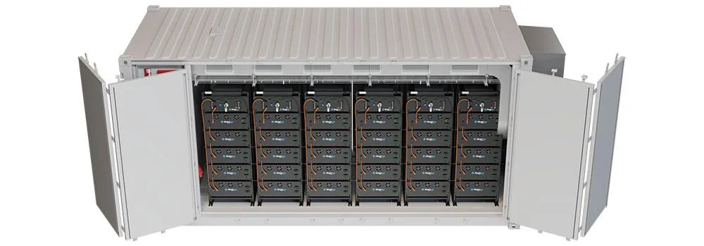
Sodium-ion storage moved from pilot to purchase order in 2026: a 60 GWh supply agreement,
Read article
Elena Vasquez is a power electronics application engineer with 10 years of experience integrating laminated busbars into EV inverters, charging systems and energy-storage PCS. She specializes in low-inductance DC-link design, EMC behaviour and converter packaging, and holds a B.Sc. in Electrical Eng
Send the current profile, voltage class and terminal types — our engineers reply within one business day.