800 V DC distribution has moved from EV traction into data centers, marine systems and solar-storage clusters — the Open Compute Project's 800 VDC specifications, joint 2026 whitepaper with NVIDIA, Google and Microsoft, and the July 2026 LVDC Solid-State Transformer specification v0.3 all point the same way. For busbar designers, the shift from 400 V AC to 800 V DC is not a matter of doubling the voltage rating. DC changes how voltage distributes across insulation, how pollution forms leakage paths, how partial discharge behaves at altitude, and how faults develop. This guide walks through the physics and the practical design rules for insulating a laminated busbar at 800 V DC.
800 V DC distribution has moved from EV traction into data centers, marine systems and solar-storage clusters — the Open Compute Project's 800 VDC specifications, joint 2026 whitepaper with NVIDIA, Google and Microsoft, and the July 2026 LVDC Solid-State Transformer specification v0.3 all point the same way. For busbar designers, the shift from 400 V AC to 800 V DC is not a matter of doubling the voltage rating. DC changes how voltage distributes across insulation, how pollution forms leakage paths, how partial discharge behaves at altitude, and how faults develop. This guide walks through the physics and the practical design rules for insulating a laminated busbar at 800 V DC.
AC and DC do not stress insulation the same way. In AC systems, voltage reverses every half cycle and capacitive coupling dominates how voltage divides across a series insulation stack. In DC systems, voltage distributes according to resistance, not capacitance — which means surface contamination, humidity films and edge paths set the actual potential gradient. A busbar that passed a 1,500 V AC hipot can still track across a wet, dirty surface at 800 V DC because the DC leakage path follows resistance, and pollution lowers that resistance where it concentrates. This is the first rule of DC insulation design: design for the DC voltage distribution, then verify with DC testing. The creepage and clearance design guide covers the general framework; this article applies it to the 800 V DC class.
Standards treat DC withstand differently from AC. IEC 60664-1 defines working voltage for DC as the continuous voltage value, and the required clearance for DC is derived from the peak voltage but without the repetitive-transient burden AC carries. In practice, for 800 V DC busbars the industry targets DC working voltage plus margin — commonly 1,100–1,300 V DC withstand — and adds pollution-degree and altitude corrections from IEC 60664-1 and IEC 62477. A useful rule of thumb for the dielectric stack: an 800 V DC laminate typically needs the same film thickness class as a 690 V AC design, but with stricter edge sealing and creepage because of the DC tracking mechanism. Designers should always verify against the design guide and the relevant standard for the target market.
Clearance is the shortest air path between conductors. For 800 V DC, the clearance requirement is driven by the peak voltage (the 800 V nominal with ripple margin) and by transient overvoltage from the system. In data-center and storage environments the overvoltage category is usually II or III, which sets the impulse-withstand voltage and therefore the clearance. Practical numbers: for pollution degree 2, overvoltage category II, the required clearances for ~1,000 V peak are on the order of a few millimeters — but every installation should compute them from the actual standard rather than copy a table. The laminated busbar geometry, with insulation between layers, replaces air clearance inside the stack; air clearance still matters at terminals, exposed edges and mating hardware, where insulators and standoffs extend the air path.
Creepage is the surface path between conductors, and it is where DC systems fail most often. In DC, leakage current polarizes contamination and drives electrochemical tracking — carbonized paths grow across the surface over time. The IEC 60664-1 creepage tables depend on working voltage, pollution degree and the material's CTI (comparative tracking index). For 800 V DC, pollution degree 2 and a CTI ≥ 600 material, creepage requirements typically fall in the 8–14 mm range depending on the standard edition and material class. PET, Nomex and DLF films differ in CTI, which is exactly why dielectric material selection and creepage design must be done together: the film choice sets the CTI, and the CTI sets the required creepage distance.
Partial discharge (PD) is the biggest difference between designing a 400 V busbar and an 800 V one. PD starts in air gaps inside or at the edge of the insulation — voids in lamination, bubbles at edges, delaminated film — and it erodes the insulation slowly until failure. At 800 V DC the PD inception voltage (PDIV) margin is tighter than at 400 V, and altitude makes it worse: PDIV drops roughly 15–20% per 1,000 m above sea level because air density falls. A busbar PD-free at sea level may not be PD-free at a 2,500 m site. The engineering answer is PD verification on production-representative samples at the expected altitude correction, which is what SHANYUAN does on quality and testing for 800 V-class programs. The PD-free design guide details the mechanisms.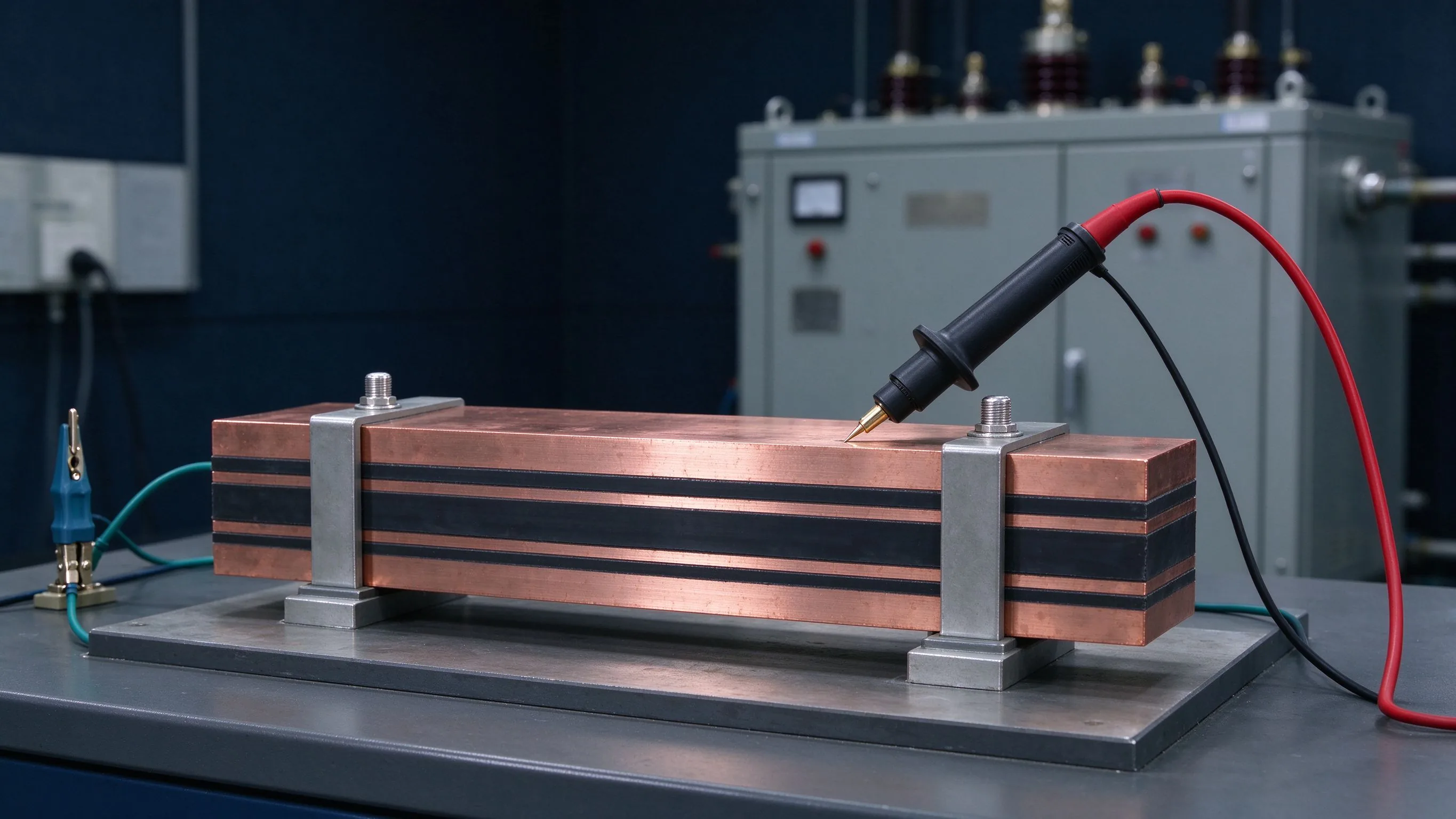
Laminated busbar failures at DC almost always start at the edge. The edge is where film thickness ends, where a burr can be, where plating can creep, and where humidity wicks. Edge sealing — a cured insulating edge band or overlap of the dielectric beyond the copper — is the single most important manufacturing detail for 800 V DC. It must survive handling, thermal cycling and the assembly environment without cracking or lifting. SHANYUAN's lamination process extends the film beyond the copper edge and seals the perimeter, then verifies with hipot and PD on finished parts. When an 800 V DC busbar is specified, ask the supplier how the edge is sealed and how the seal is verified — the answer tells you more than the film data sheet.
Creepage and clearance both depend on pollution degree, and for DC systems the enclosure decides it. A sealed 800 V DC distribution unit can hold pollution degree 2 (non-conductive pollution, occasional condensation); an open rack in a dusty hall drifts toward degree 3, which roughly doubles creepage requirements. The design implication: the busbar spec and the enclosure spec are one decision. Data-center 800 VDC deployments, per the OCP trajectory, favor sealed power shelves precisely to keep pollution degree low and creepage compact. Specify the pollution degree on the RFQ; it is the parameter that silently changes both clearances and creepage distances.
These five checks convert an 800 V DC busbar from a drawing risk into a verified component. The low-inductance design and thermal management guides cover the other two legs of the design stool.
An 800 V DC bus is not a clean 800 V. Inverter and converter operation adds ripple, and load steps add transients that can peak well above nominal. The insulation design should use the worst-case peak including ripple and transient allowance as the working voltage for clearance and PD margin, not the nameplate 800 V. This is where a 1,100 V or 1,300 V DC withstand target comes from — it is the engineering allowance for real waveforms. Specify the ripple and transient envelope on the RFQ so the supplier designs to the actual stress. The electrical spec is a conversation about waveforms, not a voltage box on the drawing.
The OCP 800 VDC specifications, the March 2026 joint whitepaper with NVIDIA, Google and Microsoft, and the July 2026 LVDC Solid-State Transformer specification v0.3 with 80+ participating manufacturers are pushing data-center power distribution toward 800 V DC shelves — and the same voltage logic applies to green-power direct-connect clusters. For busbar suppliers this means a repeatable product category: 800 V DC distribution busbars with sealed insulation, documented PD performance and rack-optimized geometry. The copper-mass math is part of the story — OCP estimates a 1 MW rack at 54 V would need roughly 200 kg of copper busbar; at 800 V the same power needs a fraction of that. SHANYUAN's power-electronics busbars for this class are built on the same lamination platform used for traction and storage, so the insulation learnings transfer directly.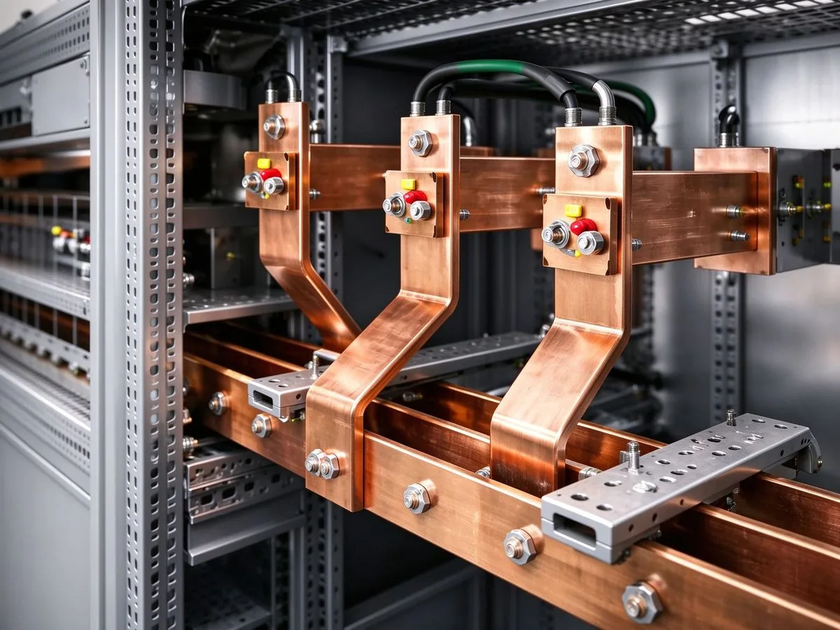
For 800 V DC, the stack decision starts with voltage class and CTI: PET for cost-effective PD2 environments, Nomex where thermal class and tracking resistance matter, DLF epoxy where rigidity and edge finish are critical. Layer count follows the current path — interleaved positive and negative layers for low inductance — and each layer adds to the insulation duty. The film thickness is then chosen for the DC withstand plus margin, with edge extension and sealing added as design rules. SHANYUAN documents the stack — film type, thickness, layer count, edge extension — on every 800 V-class drawing, so the design is auditable through the whole certification chain. The custom design service reviews the stack against your actual voltage, pollution and altitude conditions before tooling.
Design the 800 V DC busbar around DC physics, not AC habits. Size clearance for the peak including ripple; size creepage for pollution degree, CTI and DC tracking; verify PD at the operating altitude; seal the edges; and test with DC hipot plus PD on production-representative parts. Document the stack, the standard edition and the test data, and pair the insulation with the contact-finish choice, and put the ripple/transient envelope on the RFQ. Done this way, 800 V DC distribution stops being a risk and becomes a standard engineering task — the same progression EV traction followed a decade ago. For a design review of your 800 V DC busbar, contact SHANYUAN — the engineering team answers with numbers, not adjectives.
A busbar fails quietly when a void inside its insulation starts discharging. This guide co
Read articleAI racks move from 140 kW to 1 MW by 2027, and the industry answers with 800 VDC distribut
Read article
Daniel Richter is the chief electrical engineer at SHANYUAN Laminated Busbars, with 15 years in laminated busbar design and current-carrying systems. He leads electrical dimensioning, DC-link layout and thermal simulation for power converters, EV platforms and HVDC stations, and holds an M.Sc. in El
Send the current profile, voltage class and terminal types — our engineers reply within one business day.
