AI compute density has outgrown the 54 V busbar. In March 2026 NVIDIA, Google and Microsoft published a joint 800 VDC architecture under the Open Compute Project, and more than 80 companies are now building to the specification. For power engineers, the shift from 54 VDC to 800 VDC distribution changes what a busbar has to do: the currents drop by an order of magnitude, the insulation coordination voltages roughly triple, and stray inductance moves to the top of the design checklist.
AI compute density has outgrown the 54 V busbar. In March 2026 NVIDIA, Google and Microsoft published a joint 800 VDC architecture under the Open Compute Project, and more than 80 companies are now building to the specification. For power engineers, the shift from 54 VDC to 800 VDC distribution changes what a busbar has to do: the currents drop by an order of magnitude, the insulation coordination voltages roughly triple, and stray inductance moves to the top of the design checklist.
Rack power has doubled roughly every generation of AI hardware. Vertiv reports that AI racks already draw 140 kW with 240 kW close behind, and 600 kW designs are in the 2026 planning horizon. NVIDIA's Kyber rack-scale system, scheduled for 2027 with 576 Rubin Ultra GPUs, is quoted at megawatt-class IT per rack.
At 54 VDC, a 1 MW rack needs about 18,500 A of distribution current — a conductor and busbar problem that grows faster than the power it serves. At 800 VDC the same rack needs roughly 1,250 A. Higher distribution voltage reduces conductor mass, simplifies the power path, and removes conversion stages between the facility and the chip. That is the physics behind the joint NVIDIA, Google and Microsoft position paper published in March 2026 and the OCP Power Distribution project's LVDC work, which now covers up to 1,500 VDC and keeps the ±400 V Mt. Diablo sidecar specification.
For laminated busbar suppliers the change is not cosmetic: the DC-link of an 800 V power rack is a low-inductance laminated assembly operating in a high-transient environment, and it is specified by a different voltage class than any 54 V part in the same building.
NVIDIA's roadmap stages the transition in three overlapping deployment patterns rather than one forklift change. First, the power rack / sidecar (H2 2026): an 800 VDC power center placed beside an MGX-compatible rack, fed by existing AC infrastructure, delivering 800 VDC to the compute over a busbar tied to the GPU rack. Vertiv's PowerDirect 5000 is the reference sidecar, delivering 400–900 kW directly into the rack. Second, the row power center (2027): a centralized power station feeding an overhead 800 VDC busway at up to 2 MW per row. Third, the DC power block for new facilities: medium voltage to 800 VDC in one conversion step via solid-state transformers or industrial rectifiers.
Each stage moves the laminated busbar one step closer to the load — from switchgear to the row busway, and finally to the rack-side DC-link where inductance, partial discharge and thermal density are all active design constraints.
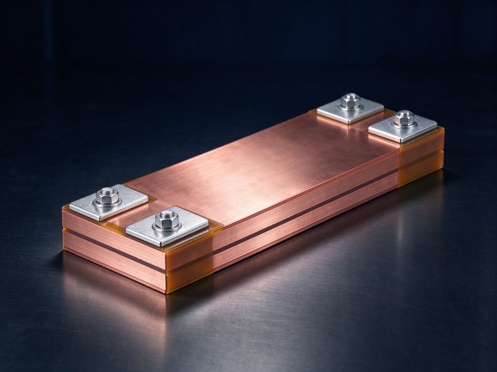
The relationship is simply P = V × I. Delivering 800 kW at 54 VDC needs ~14,800 A; at 800 VDC it needs ~1,000 A. The cross-section of a copper conductor scales with current, so an 800 VDC distribution can use dramatically lighter rails, thinner power distribution runs and smaller enclosures.
NVIDIA's own estimate is that 800 VDC can reduce conductor requirements and simplify or eliminate conversion stages depending on the facility design, and operators report fewer in-rack power supply failures as an additional maintenance benefit of removing stages. For the busbar itself, lower current means more margin for a given cross-section: a DC-link laminate rated for 1,250 A continuous at 800 VDC is a comfortable design with a 2–3 mm copper layer pair, where the same power at 54 V would have pushed the same laminate into parallel-layer territory with severe thermal management demands.
Current density practice for laminated assemblies — typically 1.2–2.0 A/mm² under natural convection in a rack — now has headroom, but only if the thermal budget is verified with the thermal management rules that apply to enclosed electronics.
Insulation coordination treats DC differently from AC because DC has no zero crossings: a sustained voltage stresses the insulation continuously. IEC 60664-1 (Clause 4.2) applies a 1.5× factor for DC systems, so an 800 VDC busbar is coordinated at the equivalent of 1,200 VAC peak conditions. Clearance and creepage distances on the laminate, around studs, and across terminal gaps must be dimensioned for that equivalent, not for a nominal 800 V label.
This is where power electronics busbar design and partial discharge control meet: at 1,200 V equivalent stress, the dielectric selection, PET or Nomex layer count, edge termination and the insulating film stack all move up one class relative to conventional 400 V inverters. A 800 VDC laminate is a genuinely different product from a 54 V rack busbar even when the outline looks similar.
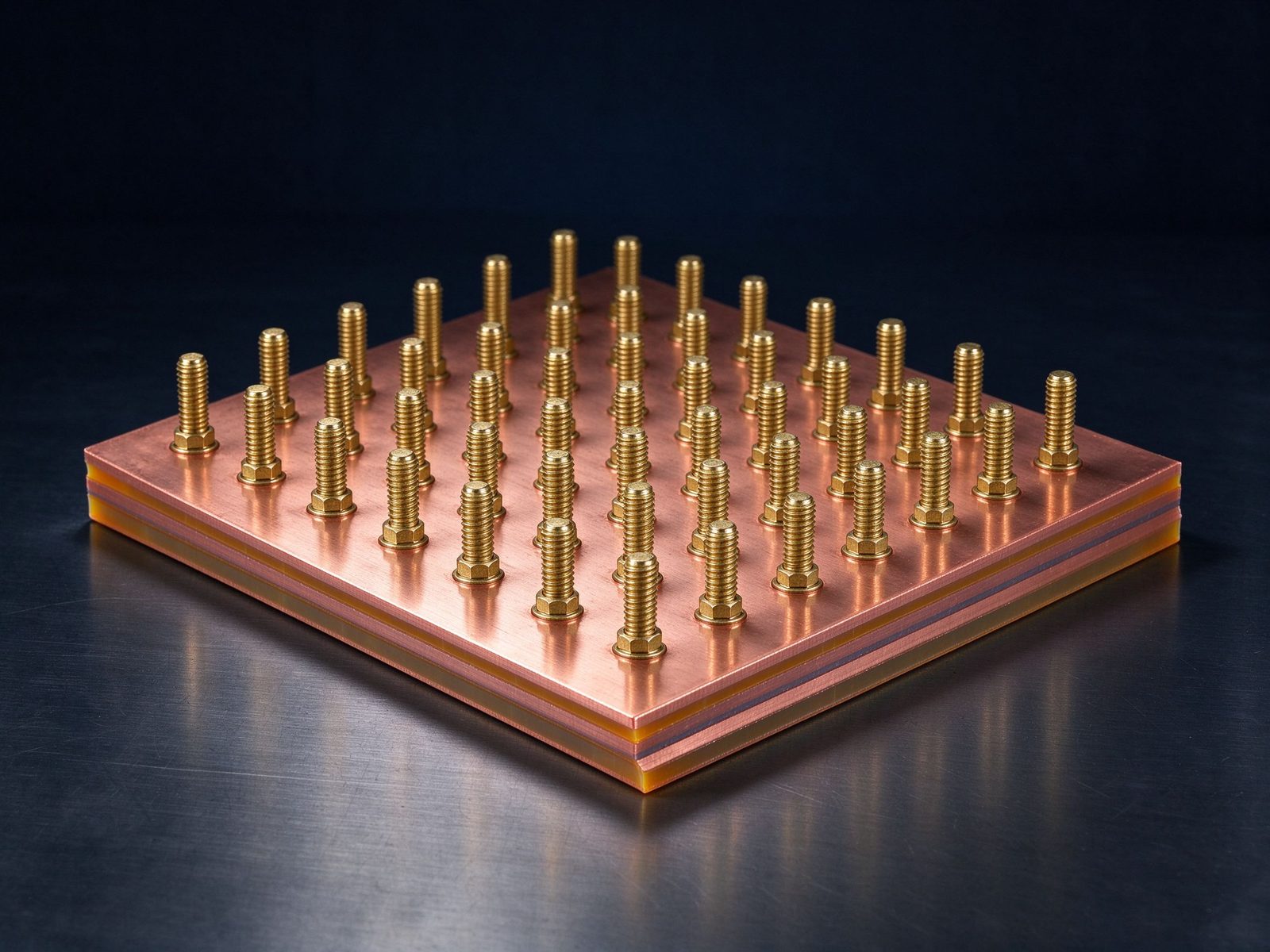
The transient currents in AI power delivery are large and fast. NVIDIA's architecture deliberately uses capacitors and supercapacitors at the rack as a low-pass filter for millisecond-to-second disturbances, with facility-scale battery storage smoothing the seconds-to-minutes band. For the DC-link between the storage, the converters and the GPU load, loop inductance directly controls the voltage overshoot during current steps: the classic L × di/dt penalty.
Laminated busbars win this argument because face-to-face conductor pairs cancel loop area. The design rules are the same ones documented in our low-inductance design reference — thin dielectric gaps, overlapping current-carrying layers, short return paths, terminals close to the capacitor bank — but the stakes are higher when the load steps are megawatts. A 10 nH reduction in the DC-link loop at a 1 MW power step is not academic; it can mean the difference between a clean switching waveform and a device voltage spike that threatens the SiC or IGBT modules.
In the 800 VDC architecture, battery backup moves onto the DC bus. Rack-adjacent BBU shelves connect to the DC-link through DC/DC converters, and facility-scale battery energy storage systems (BESS) hang off the same bus for grid stabilization. Every one of those interfaces is a busbar joint: the BBU shelf's low-voltage side, the DC/DC converter's 800 V side, and the battery string interconnect.
For the battery side of these systems, the same battery busbar engineering applies as in ESS installations — multi-layer laminates with controlled impedance, welded or bolted terminals sized for the module current — but now with an 800 VDC system voltage above them, which raises the creepage and partial discharge requirements discussed above. The energy storage application notes and the ESS PCS DC-link article cover the pack-side practice in detail.
Moving power conversion out of the rack into sidecars and row power centers concentrates the losses in a smaller envelope. A row power center serving 2 MW of IT load dissipates converter, busbar and connection losses in a pod-sized enclosure, and the busbars inside it carry most of the current. The thermal budget is set by the same ampacity calculation method we publish for switchgear: temperature rise = f(cross-section, current, surface area, enclosure ventilation).
Liquid cooling is appearing in power racks too — several vendors now offer 800 VDC power shelves with integrated cooling — and the busbar-to-cooling-plate interface becomes a mechanical and thermal design point. Tin-plated copper laminates with bonded insulating layers handle the interface well, but the heat path through the dielectric must be accounted for, which is exactly what our thermal management reference quantifies.
The 800 VDC ecosystem is being standardized in public: the OCP Power Distribution project covers up to 1,500 VDC, released a Solid-State Transformer specification v0.3, and is working with UL Solutions, NFPA, IEEE and IEC. A joint NVIDIA white paper was published in March 2026, and the OCP interoperability work is ongoing. But an open specification is not a listed product — safety listings for 800 VDC racks, busways and busbars are still being established, and the industry is working through UL and IEC processes in parallel.
For component suppliers the practical consequence is to design to the stricter envelope: IEC 60664-1 insulation coordination, UL 891-class thermal margins where applicable, and the partial discharge requirements that follow from the voltage class. Building a part that satisfies the most conservative published requirement protects the customer while the listing landscape settles.
The sidecar architecture changes mechanical interfaces. The 800 VDC busbar that ties the sidecar to the GPU rack is a rigid laminate crossing an enclosure boundary; it must manage thermal expansion, vibration and blind-mating tolerances while maintaining the insulation coordination of the DC bus. Vertiv's PowerDirect 5000 delivers power 'over a busbar tied to the GPU rack', which means the busbar is part of the mechanical alignment of the system, not just an electrical conductor.
Dimensional tolerances for such parts follow the same fabrication tolerance rules we document for stamped and formed copper, with extra attention to hole positions at the mating interface and the flatness of the connection faces.
Existing GB200 and GB300 NVL72 racks remain on the 54 V busbar through the current generation, and native 800 VDC input arrives first with Vera Rubin NVL72 in the Gen 2 platform. The transition is deliberately incremental: NVIDIA states that the 800 VDC architecture supports all existing data centers while providing a smooth path to an all-800 VDC future, and the sidecar is designed to contain the transition close to the compute.
Suppliers therefore live in both worlds for the next 24–36 months: 54 V rack busbars with their very high current densities, and 800 VDC laminates with their higher voltage class. Both are laminated busbar problems, but they pull the design in different directions — current density and thermal management on one side, insulation coordination and partial discharge on the other. A supplier that can design both is the useful partner during the transition.
800 VDC distribution introduces DC protection challenges that AC never had: DC arcs do not self-extinguish at zero crossings, so fault clearing depends on breaker design and the busbar geometry that surrounds it. The DC-link busbar layout must minimize the fault loop inductance that a protection device has to interrupt, and the physical clearance around the breaker terminals must satisfy the coordination distances of the DC voltage class.
This couples busbar design to protection engineering: terminal spacing, busbar routing around the breaker, and the placement of current sensors on the laminate are all part of the system. Early integrators report that the 800 VDC busway and breaker coordination is where the architecture stops being a rack problem and starts being a hall problem, exactly as the earlier data center busbar analysis predicted.
The 800 VDC transition amplifies demand for high-quality conductor copper and precision laminates. Rack busbar copper consumption is already rising fast — one Chinese copper processor reported rack busbar copper base material sales of 3,185 tonnes in H1 2026, up 94% year on year — and the voltage class shift adds insulation materials to the bill of materials. With LME copper at record levels, the economics of every kilogram of conductor are under review, and the aluminum versus copper trade-off is being evaluated for the less demanding distribution sections of the same facilities.
From our engineering review of the published architectures, an 800 VDC DC-link laminate should be specified against at least these six constraints: (1) insulation coordination at 1.2×–1.5× the nominal DC voltage per IEC 60664-1; (2) partial discharge margin across the operating voltage range; (3) loop inductance budget set by the converter's di/dt and module voltage rating; (4) continuous current density verified by temperature-rise calculation, not by rule of thumb; (5) terminal and mounting geometry coordinated with the power rack mechanical interface; and (6) protection coordination with the DC breaker and sensor placement. A custom design review against the actual power profile is the reliable way to lock these down before tooling.
NVIDIA ties full-scale production of native 800 VDC data centers to the Kyber rack-scale systems in 2027. Vertiv's sidecar deployments begin in 2027, row power centers follow, and DC power blocks are the decade-ahead drawing for new facilities. For system planners the message is that 2026 is the year to prototype: qualification units, sidecar-compatible busbars, and the documentation chain for UL and IEC listings should all be started now so that 2027 programs do not wait on the power path.
Component suppliers with existing inverter DC-link busbar lines and power electronics busbar capability are well placed to serve the transition, because the manufacturing processes — lamination, terminal attachment, precision stamping — are the same; only the electrical specification envelope changes.
The 800 VDC transition is a system change, and busbars sit at every system boundary: the rectifier output, the busway distribution, the rack-side DC-link, and the battery interfaces. The practical value of a laminated busbar supplier in this environment is not just the part — it is the DFM review that catches a voltage class, inductance or thermal issue before tooling, and the documentation that supports the customer's safety listing work.
SHANYUAN manufactures laminated busbars for power electronics, energy storage and data center applications with exactly this discipline: layer stacks from 1 to 6+ conductors, C11000 copper, PET/Nomex/DLF dielectrics, tin-plated surfaces, and M6/M8 stud, blade or welded terminals. If your 2027 program is moving to 800 VDC, send the power profile and mechanical envelope — our engineers will return a DFM assessment and a quotation within one business day.
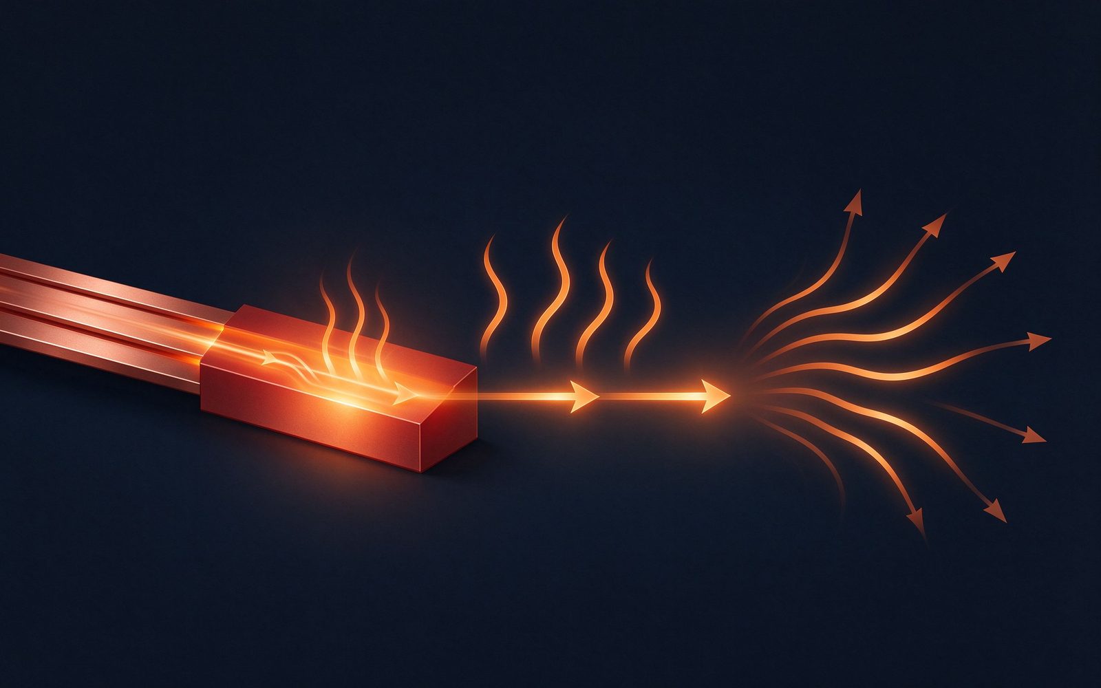
A busbar's rating is not a lookup — it is a calculation. Temperature rise is the real limi
Read article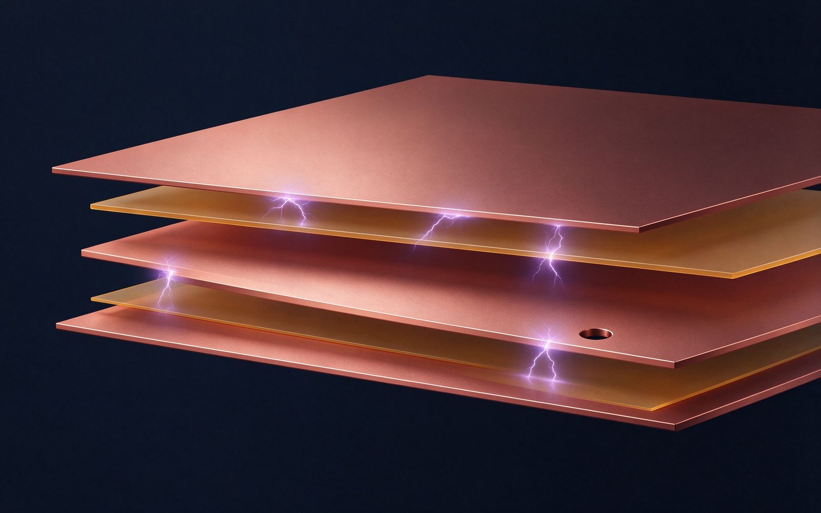
A busbar fails across a surface long before it fails through its insulation if the creepag
Read article
Record copper prices, a 4.41 copper-to-aluminum price ratio and a structural supply gap fo
Read articleSend the current profile, voltage class and terminal types — our engineers reply within one business day.
Send drawings, current ratings and voltage class — DFM feedback and a quotation within one business day.
