A flexible busbar replaces a rigid hard joint between two points that move relative to each other: vibrating equipment, thermal-expansion mismatch, space-constrained assemblies. This guide covers how lamella stacks work, the ratings you design to, and when flexible wins over rigid or cable.
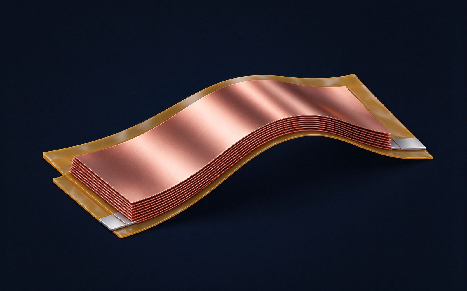
A flexible busbar is not a bent rigid laminate. It is a stack of thin, pure-copper lamella sheets enclosed in protective insulation, typically PVC, with or without rigid end parts, tin-plated or bare. The thin individual foils can slide against each other inside the jacket, which is what makes the whole assembly bendable in the field and tolerant of movement.
Construction details matter more than they look. The lamellas are thin pure-copper sheets, each flexing independently, stacked to the total cross-section the current requires. Each foil is insulated within the common PVC jacket, so the stack can flex without the foils wearing through each other. Tin-plated lamellas are standard for corrosion resistance and joint stability; bare copper is an option where cost dominates and the environment is benign. Rigid end parts, when specified, carry the bolted interface, while the flexible middle section does all the moving.
It is worth being explicit about what a flexible busbar is not. It is not a rigid laminate with the middle section thinned down, and it is not a braided strap in shrink tubing. The lamella stack is engineered as a system: individual thin foils sized for fatigue life, stacked to the current, enclosed in a jacket chosen for flame class and temperature, and terminated with end parts sized for the bolt load. Treating it as a generic flexible strap is how designs end up with cracked foils at the clamp after a year of duty cycles.
Electrically, all the lamellae in parallel carry the current; mechanically, the stack behaves like a spring: it flexes under differential displacement while staying clamped at both ends. Standard and customized lengths are available, and the part installs quickly because no field forming of rigid buswork is needed. For how this differs from the rigid laminated family, our laminated busbar design guide sets out the full construction chain.
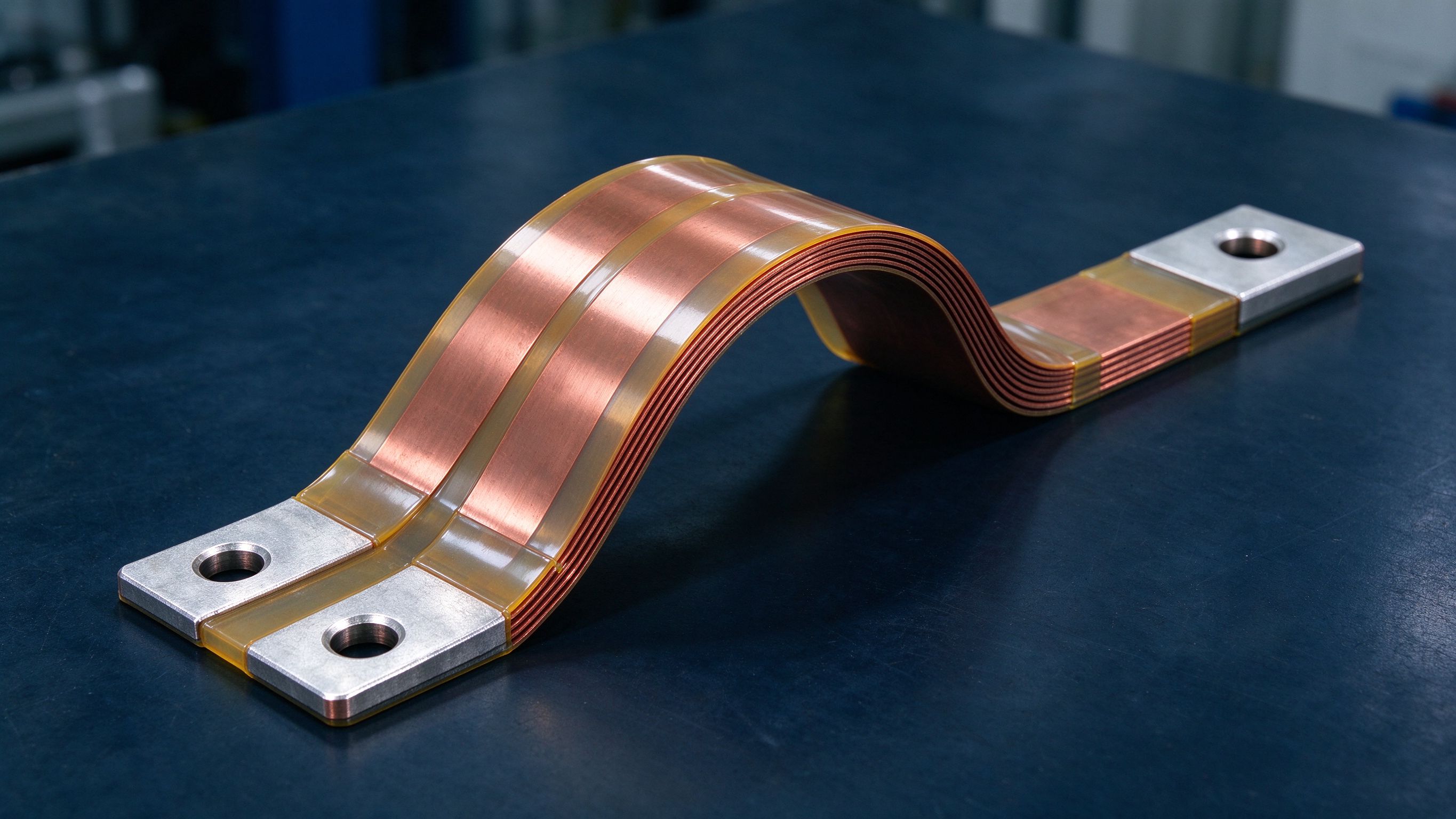
A rigid busbar clamped between two heavy components turns every vibration cycle into a mechanical stress at the joint. In EV powertrains, commercial vehicles and rail equipment, pack-level shock and vibration profiles are severe, and the harshest environments are exactly where power electronics cannot afford a loosened bolt or a fatigued lug.
Quantitatively, the environment is harsher than a bench test suggests. Pack-level vibration in EV and commercial-vehicle duty runs for the vehicle's whole life, and rail equipment is qualified to its own shock and vibration regimes, referenced in industry standards such as EN 61373. A rigid bolted bar between a vibrating inverter and a fixed chassis converts every acceleration into a fatigue load at the fastener; a flexible stack converts the same acceleration into harmless micro-bending of thin foils, which are engineered to tolerate millions of cycles.
A flexible lamella stack absorbs that vibration at the source: the joint stays torqued, and the flexibility lives in the middle of the conductor instead of at the fasteners. This is why flexible constructions are the default choice where vibrating parts have to be connected, from EV battery modules and powertrains to rail traction and auxiliary converters, and it pairs naturally with energy storage systems, where rack-level vibration and thousands of bolted cells make joint loosening the classic field failure. The mechanical stress problem, not the electrical one, is usually the reason a designer switches from rigid buswork to a flexible interconnection.
Where this shows up in products: pack-level current distribution between modules, the connection from the pack fuse box to the inverter input, and machine terminals on vibrating frames. In each case the failure mode being bought out is the same: a rigid connection that fatigues at the fastener. UPS systems and drive systems are the quiet repeat buyers: the rectifier or drive sits on a vibrating floor slab, the output bus runs to a cabinet that shifts slightly over years of thermal cycling, and a flexible stack between them removes the joint as a maintenance item. If your vibration profile includes repeated shock, potholes, rail over bumps, crane lifts, the flexible stack is the conservative choice, because its fatigue life is measured in millions of micro-bends rather than thousands of big ones. Where the displacement budget is tight, the stack is simply lengthened in the flex zone, at almost no extra cost.
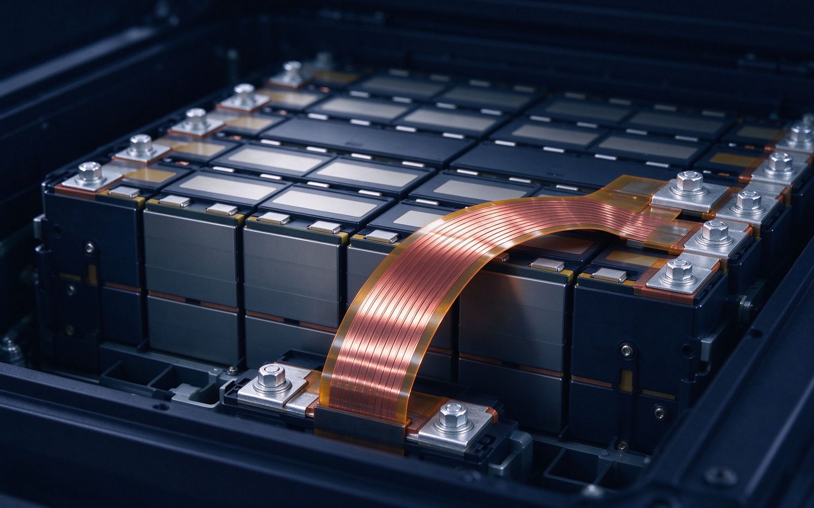
Every power assembly heats up and cools down. Copper busbars, aluminum housings and steel frames expand by different amounts, at different rates. A rigid joint clamped between two thermally mismatched components accumulates cyclic stress every duty cycle, the classic slow path to a loose bolted connection or a cracked terminal.
Put the stress in perspective. A 300 mm copper bar swinging through a 60 °C temperature cycle grows by about half a millimeter or more per end, and if both ends are rigidly bolted, that growth has nowhere to go: the joint bends, the bolt relaxes, contact resistance creeps up, and the joint heats itself further. The lamella stack absorbs exactly this displacement in the flex zone.
Rated for −40 °C to +105 °C as standard, with special insulation extending to 125 °C, the flex zone does mechanical work the entire life of the part: tolerance compensation at assembly, differential expansion in service, vibration on the road, all while the clamped ends stay torqued. The design input this demands is the displacement budget, not just the static positions. Measure or estimate how far each end moves, in which directions, and how often; a stack sized for the static drawing but not the thermal growth will bottom out the flex zone on the first hot day. Send us the temperature cycle range and we will size the free flex length against the expected growth, with margin for the worst-case cycle. Pair this with the lifetime math in our thermal management guide when you size the continuous rating.
Flexible busbars are a low-voltage interconnection solution, not a high-voltage one. Keep the voltage expectations in the right band:
| Parameter | Typical range |
|---|---|
| Voltage | up to 1 kV AC / 1.5 kV DC |
| Ambient temperature | −40 °C to +105 °C; special insulation to 125 °C |
| Flammability | Highly flame-retardant insulation, VW-1 per UL 1581 |
| Current | Set by total lamella cross-section, see note |
Read the table as boundaries, not targets. Up to 1 kV AC / 1.5 kV DC means flexible stacks belong on the distribution and connection level: battery packs, charger outputs, machine terminals, not inside a traction converter's high-voltage DC link, where rigid laminated construction with controlled creepage is the right tool. The VW-1 flame class per UL 1581 covers the PVC jacket; rigid laminates can also meet UL 94 V-0 class constructions, so ask us at DFM if flammability is a named customer requirement. Humidity and sealing are the other design variable: the PVC jacket seals the foils against moisture and dust, and tin-plated foils protect the contact faces; for harsh environments, salt spray under trucks or offshore cabinets, the jacket material and terminal plating are questions to raise at DFM, not after first article.
The current rating is set by the summed cross-section of the lamellas; size it exactly as you would size any other conductor, with the temperature rise and derating factors in our ampacity chart. One caveat versus a rigid laminate: the foils slide loosely inside the jacket, so the stack does not give you the tight plane-to-plane coupling of a bonded laminate. If your application needs both movement tolerance and a low-inductance commutation path, the usual architecture is a rigid laminated DC link with a flexible stack on the non-critical feeders, not a single part trying to do both. If switching speed and loop inductance are the spec, the DC link should stay rigid; our low-inductance design guide covers where the boundary sits.
Think of the decision as a triangle of needs. Rigid laminated busbars optimize inductance, compactness and high voltage; cable harnesses optimize unrestricted routing and reworkability; the flexible lamella stack optimizes movement tolerance between two fixed points. It wins specifically where the two endpoints are fixed in space but relative motion exists between them:
It loses where the routing itself must change between variants; then a cable is still the honest answer. The boundary with cable is also where assembly time pays: a flexible stack arrives as one bent-to-shape part with terminals already attached, two bolts and it is installed, with no routing, no lug crimping, no torque checklist per wire. At volume, that assembly simplicity is often the real reason the flexible stack wins over a cable harness on a moving joint, quite apart from the vibration argument. Compare the full trade-off in our busbar vs cable harness guide; most production equipment uses rigid laminates for the high-current power paths and flexible or cable for the moving joints. For battery work specifically, our copper battery-link busbar pair and the trends note on EV battery busbars cover the pack-level detail.
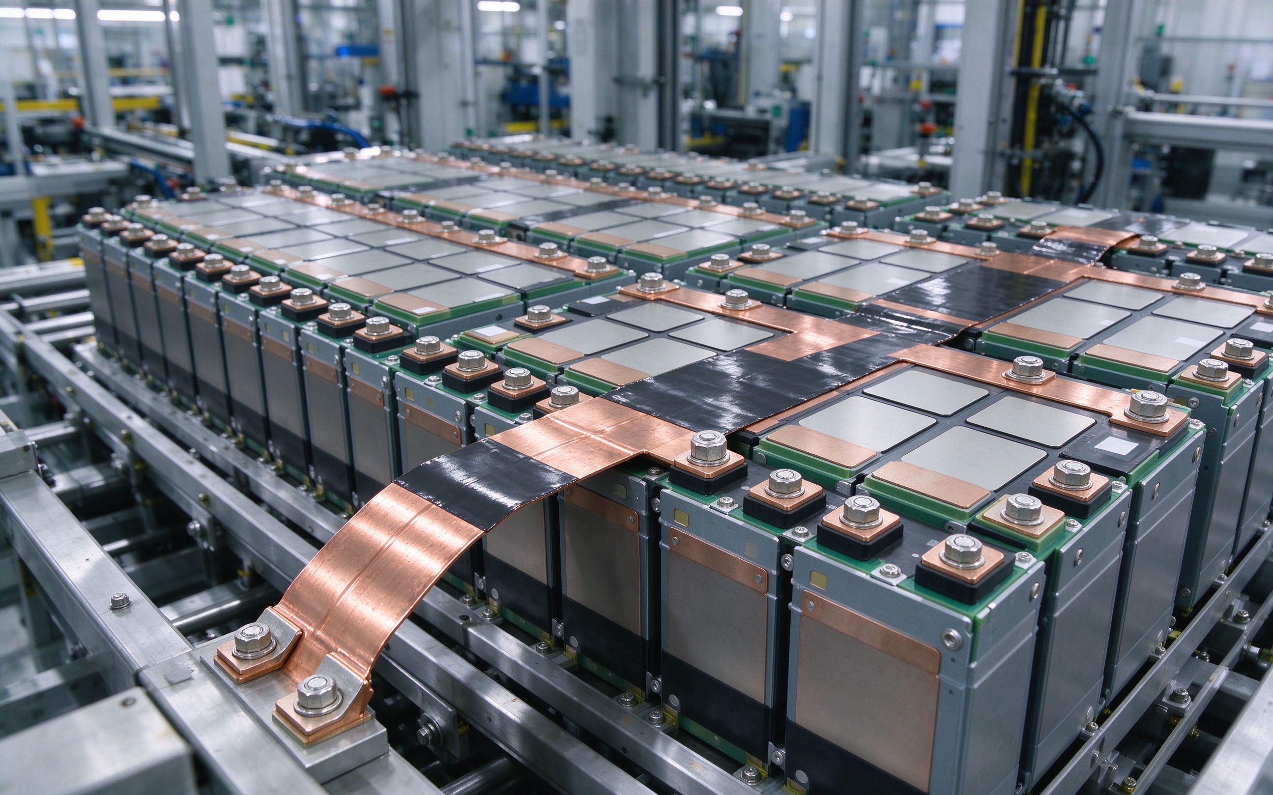
Two mistakes we see repeatedly. First, designing the bend into the clamped end: the fatigue life of a lamella stack comes from letting the flex zone float freely; bending right at the clamp cracks the foils in months. Second, undersizing the cross-section for the enclosure: thin stacks look like they cool for free, but a sealed chassis kills the convection the rating assumes. One last rule: keep the flexible stack out of the commutation loop. It absorbs movement well, but its loosely stacked foils do not cancel magnetic flux the way a bonded laminate does, and a flexible interconnection carrying switched DC-link current will radiate more EMI than the rigid alternative. Put the flex on the battery feed, the charger output, the machine terminal, not between the capacitors and the switches.
Ready to size one? Start from the design guide checklist, or send your sketch through contact engineering. The pattern across this guide repeats: the flexible stack is bought for movement tolerance, rated as a conductor, and terminated like a joint. Get those three boundaries right and the rest is standard laminated manufacturing.
Send the current profile, voltage class and installation conditions — we will size the busbar and document the calculation with your quotation.
Send the current profile, voltage class and installation conditions — we will size the busbar and document the calculation.
