In July 2026, Joby Aviation re-baselined its certification programme, moving type certification of the Valo aircraft from 2028 to 2029 while confirming progress on piloted transition flight testing. In May, the EU's Clean Aviation HECATE programme announced it had matured electrical distribution technologies across 800V, 540V and 28V — power conversion, protection, connectors, cabling and EMI — with 38 partners across 11 countries and no scope reductions. Together these milestones define where eVTOL power distribution stands in 2026: the voltage architectures are settling, the certification rules are concrete, and the hardware that carries the energy — including laminated busbars — has to meet aviation-grade weight, fault and altitude requirements that ground equipment never sees.
In July 2026, Joby Aviation re-baselined its certification programme, moving type certification of the Valo aircraft from 2028 to 2029 while confirming progress on piloted transition flight testing. In May, the EU's Clean Aviation HECATE programme announced it had matured electrical distribution technologies across 800V, 540V and 28V — power conversion, protection, connectors, cabling and EMI — with 38 partners across 11 countries and no scope reductions. Together these milestones define where eVTOL power distribution stands in 2026: the voltage architectures are settling, the certification rules are concrete, and the hardware that carries the energy — including laminated busbars — has to meet aviation-grade weight, fault and altitude requirements that ground equipment never sees.
Certification, not first flight, is what turns an eVTOL program into a supply chain. Joby's July 2026 announcement re-baselined Valo type certification to 2029 after piloted transition flight testing, citing the remaining certification workscope — including certification-conforming aircraft build and test — as the driver. China's CAAC published its special conditions for electric propulsion systems, and its electrical-system rules require that power distribution safely transmit energy such that power loss, malfunction or interruption faults do not lead to hazardous consequences under the applicable engine failure provisions. The pattern across regulators is consistent: distribution networks — the buses, connectors and protection between battery and motor — are first-class certification objects, not afterthoughts. Component suppliers should design to the rules as they are written today, because the power-electronics busbar in a certified aircraft is a serialized, traceable part.
HECATE's delivery across 800V, 540V and 28V is a useful map of the industry: high-voltage DC buses for propulsion, mid-voltage for auxiliary power, and 28V for avionics. On the propulsion side, 800V has become the de facto target — dual-channel 800V DC distributed buses with surge margins in the 1,200V range appear in certified powertrain architectures, with SiC inverters at the nacelles. For a busbar designer the consequence is a high-voltage, high-current DC network in a weight-critical airframe: the bus must carry hundreds of amps at 800V, survive fault transients toward 1,200V, and do it in a structure measured in grams. The insulation and creepage and clearance rules for aircraft are stricter than ground equipment because altitude changes the game.
At altitude, air pressure drops and so does the dielectric strength of air. The same creepage distance that is safe at sea level can flash over at cruise altitude, which is why aircraft high-voltage design derates clearance with altitude and leans on solid insulation instead of air gaps. Laminated busbars are structurally well suited: the dielectric film between planes is a solid insulation system that does not depend on air, so a laminated assembly can hold 800V+ with compact geometry where an air-insulated bus would need centimeters of separation. The partial-discharge engineering that converter designers apply on the ground becomes mandatory in the air, because a void that discharges quietly at sea level can grow into a failure at altitude with thermal cycling. Specifying PD-free laminated construction for eVTOL buses is not a luxury.
Aviation rules push architecture toward fail-safe distribution: dual-channel buses, physical separation of redundant paths, and fault isolation that removes a failed source or load within milliseconds. Certified eVTOL powertrains use pyrotechnic isolation on the high-voltage DC bus — an explosive cut that physically opens the circuit under fault — plus surge suppression at the inverter inputs. For busbar engineers this means two design duties. First, the bus itself must be split into independently isolatable segments, each with its own sense points. Second, the busbar must coexist with the isolation hardware: pyrotechnic devices, contactors and current sensors mount directly on the bus, which drives terminal layout, mounting features and mechanical clearances. The custom busbar design process for such programs is as much mechanical integration as electrical sizing.
Morgan Stanley's updated urban air mobility analysis projects a $1 trillion TAM by 2040 in the base case and $9 trillion by 2050, but the engineering currency is specific power — watts per kilogram. Every gram of copper, dielectric and connector on the bus is payload lost. NASA's own high-voltage (800V) electric aircraft battery studies optimize busbar connections for low thermal and electrical resistance while managing mass, integrating the bus with cooling. The trade-offs are concrete: copper maximizes conductivity but weighs 8.9 g/cm³; aluminum halves the weight of a given cross-section at 61% IACS conductivity; composites and expanded foils add surface for cooling at the cost of complexity. The copper-versus-aluminum analysis on this site gives the numbers, and eVTOL programs push the same decision to a tighter budget.
The isolation architecture also dictates busbar segmentation: each battery string, each nacelle inverter and each distribution node gets a disconnect point, and the busbar layout must put mechanical clearance around those points so the pyro cut or contactor can open without arcing to an adjacent plane. In practice this means the high-voltage bus is designed as several short, isolated segments joined by serviceable links rather than one long continuous bar — easier to segment, easier to inspect, easier to replace. The trade-off is slightly more junction resistance and weight, which the certification rules more than justify. Busbar engineers working on these programs spend as much time on mechanical clearance, mounting and isolation geometry as on current capacity, because the fault case, not the steady state, sets the layout.
Takeoff demands maximum power: a multi-megawatt-class eVTOL pulls kiloamps from the battery through the DC bus to four or more nacelle inverters. The current isn't steady — rotor speed, pitch and payload modulate it — and every inverter switching event imposes a transient on the shared bus. The classic DC-link problem, familiar from low-inductance busbar design on traction inverters, repeats at higher stakes: loop inductance between the battery and the inverter must stay low or the switching transients create voltage spikes that stress the SiC modules and the insulation. Laminated busbars with interleaved positive and negative planes are the standard answer, and in an airframe the same solution also saves the weight of separate cabling and its shielding.
The weight budget shows up in component-level numbers. A certified powertrain program allocates mass to the distribution system in kilograms, and a busbar assembly that comes in 300g over budget forces a trade somewhere worse — less insulation, a thinner cell module, or a smaller payload margin. The practical design loop is iterative: size the conductor for current and temperature rise, measure the mass, and trade cross-section against cooling and plating. High-purity copper at the thinnest practical gauge, dielectric films chosen for both electrical and mechanical properties, and terminals machined to minimum envelope all pull the same direction. The custom engineering route exists to run this loop with real drawings and mass estimates rather than spreadsheet approximations.
An aircraft busbar sees a brutal environment: vibration from rotors and flight loads, thermal cycling from cold soak at altitude to hot ground operation, and humidity that ground cabinets rarely meet. Bolted joints are the weak point — they loosen, fret and change resistance. Aviation practice therefore favors welded or brazed connections where possible and controlled, locked bolted joints elsewhere, the same logic the welded busbar assembly work applies on high-vibration ground programs. Thermal expansion between aluminum structures and copper conductors must be managed with shaped transition pieces. The reliability playbook is identical to what rail and defense programs use; the certification overlay is what makes it aviation-grade.
A useful mental model: an eVTOL with four 300kW nacelle drives draws roughly 1.2MW from the battery at takeoff — at 800V that is 1,500A on the main DC bus, and at 400V (older architectures) it doubles to 3,000A, which is why the industry moved up in voltage. The busbar must carry that current with a temperature rise the airframe's thermal budget can absorb, and it must do it with a weight allocation measured in hundreds of grams, not kilograms. High-conductivity copper, thin dielectric with good thermal conductivity, and high-aspect-ratio flat planes are the toolkit. The current-sharing between parallel layers needs verification at full load, because uneven sharing turns one layer into a hot spot; the connection design notes on this site cover the parallel-path math.
Parallel-layer current sharing is the subtle part of high-current aircraft bus design. When four or six layers carry a kiloamp-class bus, manufacturing tolerance in layer thickness, dielectric gap and joint resistance creates uneven sharing — the hottest layer can carry 30–40% more than its share. Verification needs a current-injection test on the representative assembly measuring per-layer temperature or per-path resistance, not just a single end-to-end resistance reading. The design countermeasures are symmetrical layer layout, controlled lamination pressure, and generous, low-resistance terminations that force equal current into every layer. This is the same discipline used on traction and storage busbars, and it is one of the checks a buyer should put in the first-article test plan, because it is invisible in a drawing and expensive to fix after qualification.
Industrial busbars are tested to dimensional, continuity, withstand and insulation-resistance gates. Aviation parts add qualification layers: thermal cycling across the full flight envelope, vibration and shock per the airframe's spec, altitude withstand testing, and lot traceability — each part serialized with material certificates and test records. PD testing at altitude-equivalent pressure is a differentiator. For buyers the practical consequence is that aviation-grade busbar supply is a qualification program, not a purchase: drawings, material specs, test plans and factory audit come before any serial production. The quality and testing evidence a supplier can show — and verify on factory video tours — is what separates a candidate from a qualified source.
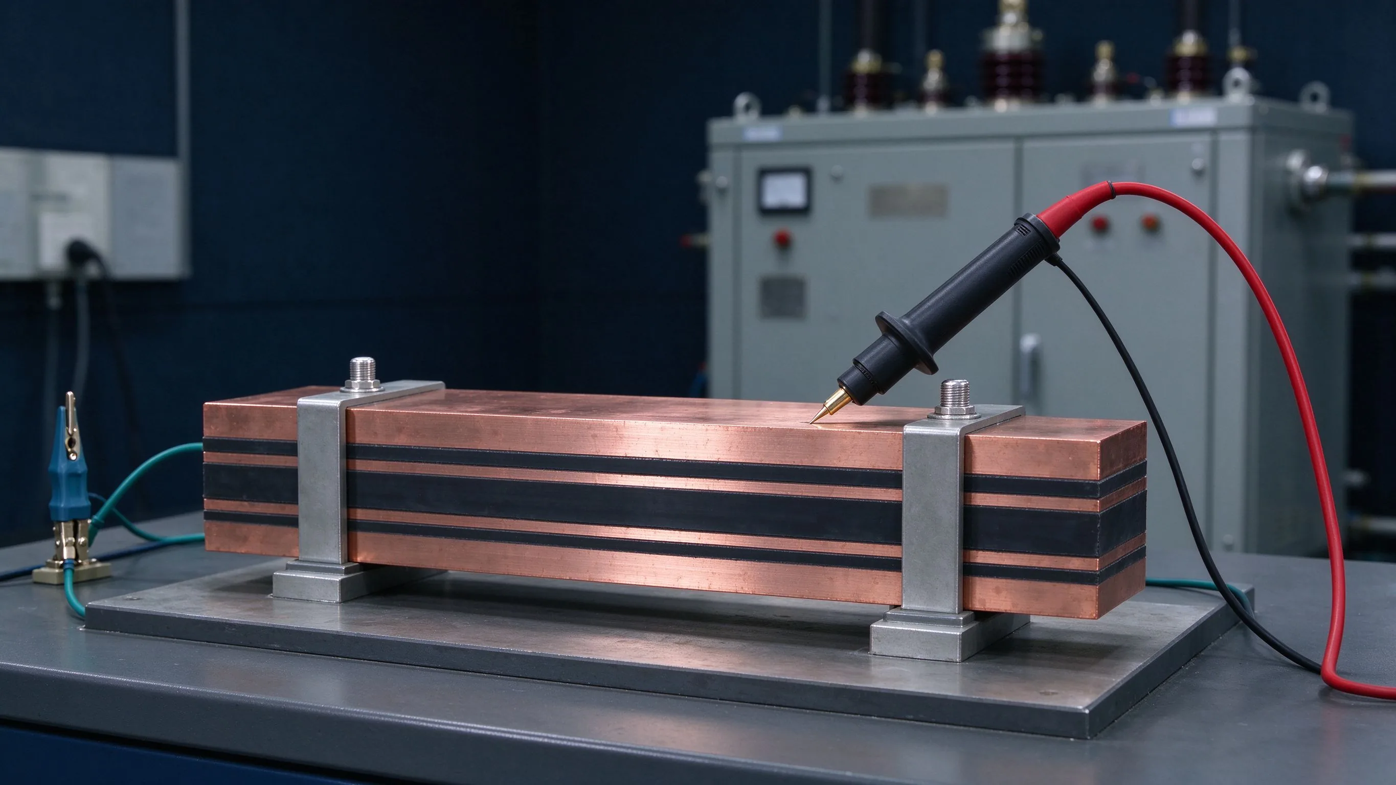
The environmental evidence extends beyond the electrical tests: humidity and condensation testing matters for an aircraft that sits on the ground in tropical conditions and climbs into cold, dry air, because the dielectric system must survive the transitions, not just the extremes. Salt-laden coastal air, cabin cleaning chemicals and maintenance fluids all belong in the environmental spec. The practical consequence is that the dielectric and plating selections are made against the full environment matrix, and the qualification evidence covers the same matrix. This is the level of engineering that separates an aviation part from an industrial part with a sticker.
Conductor selection in an eVTOL bus is a mass-optimization exercise. Copper C11000 remains the default where transients and joint reliability dominate — its 100% IACS conductivity and proven joint behavior are hard to beat. Aluminum enters where steady-state current paths can tolerate 61% IACS at half the weight, with bimetallic transitions at the copper interfaces and plating chosen for its oxide behavior. Plating itself matters more in the air: tin for corrosion resistance, silver for low contact resistance in high-cycle joints, nickel as an underlay — the same menu as terminal machining and plating but with the weight and corrosion stakes raised. Dielectric films move up the same way: PET for general duty, Nomex for thermal margins, epoxy-based systems where stiffness and conformal insulation help.
Material qualification adds its own cycle: dielectric films used in aircraft buses should be screened for outgassing, thermal endurance and resistance to the fluids an aircraft sees — hydraulic fluid, de-icing agents, cleaning solvents. PET films are the workhorse for ground laminated busbars; Nomex brings higher temperature margins and better mechanical resilience; epoxy-based systems add stiffness and conformal insulation. In an airframe, the choice between them is driven by the thermal and chemical environment more than by voltage alone. The plating question follows the same logic: tin is standard, but high-cycle silver contacts are common at disconnect points, and nickel underlayers protect against diffusion at temperature. Every material decision is a mass-and-reliability trade, which is why the terminal and plating guidance is worth reading with the airframe spec in hand.
Buyers for eVTOL programs are asking busbar suppliers questions that look like aerospace first-article questions: Do you hold material certificates per lot? Can you test at altitude-equivalent conditions? What is your PD test method and its sensitivity? Can you weld, and do you have weld qualification records? What traceability do you keep from copper coil to serialized part? The sample-to-series procurement path matters more in aviation than anywhere else, because the first article locks in a qualification that later parts must match. A structured engineering inquiry with drawings, duty cycle and test expectations in the first message is the fastest route to a serious answer.
EMI and grounding add another layer of design. An aircraft with four SiC inverters switching at 800V generates a broad conducted and radiated spectrum, and the wiring that carries control signals runs through the same structure as the power buses. Laminated construction helps twice: the interleaved planes cancel the power-loop field at the source, and the flat planes provide a low-impedance ground/return reference that shields and stabilizes nearby signal routing. The design rule is to keep control and sense wiring away from the power-plane gaps and to reference the planes properly at the inverter and battery ends. The power distribution and low-inductance design resources describe the physics in converter terms; the airframe adds only harsher routing constraints and certification evidence requirements.
Three markers shape 2027 for eVTOL distribution hardware. First, certification progress: the 2029 Valo target and parallel programmes in China and Europe mean the component qualification wave starts 12–18 months before first certified aircraft, which is now. Second, architecture convergence: 800V DC dual-channel buses with pyrotechnic isolation are becoming the reference, which standardizes the busbar form factors that suppliers tool for. Third, volume ramps: production rates measured in hundreds of aircraft per year still look small, but per-aircraft part counts and the qualification burden make the component value surprisingly large. The HVDC converter-station analysis and the data-center power trends on this site describe the same engineering — high-voltage DC, low inductance, fault isolation — in adjacent markets that are scaling today.
The qualification evidence list for an aircraft busbar program looks like this: material certificates for copper and dielectric per lot; dimensional and weight records against the drawing; dielectric withstand at the system voltage with altitude derating applied; insulation resistance at temperature extremes; PD measurement with the sensitivity and method stated; thermal cycling across the flight envelope; vibration and shock per the airframe spec; continuity and resistance records including the joint interfaces; and a serialized traceability chain from coil to part. A supplier that ships this evidence set without being asked is rare; a supplier that builds the evidence into its quality system and shows it on a factory tour is the one worth qualifying. Buyers should request the evidence matrix in the first inquiry so the program does not discover gaps at first article.
What voltage do eVTOL propulsion buses run? 800V DC has become the de facto propulsion standard, with 540V auxiliary and 28V avionics rails in HECATE-type architectures; surge margins are designed to about 1,200V. Why laminated busbars rather than cabling in an aircraft? Weight, inductance and altitude insulation: laminated planes cancel field, cut loop inductance, and use solid dielectric that does not depend on air pressure. Is partial discharge testing required? In practice, yes for 800V-class buses — altitude reduces air dielectric strength, so PD-free solid insulation is the robust design. Can a ground-equipment busbar supplier serve aviation? Only after a qualification program: material certs, altitude and thermal cycling tests, weld records, traceability and factory audit. It is a program, not a quote.
Germany's LanWin3/6, China's ±500 kV offshore VSC station and the CNY 4 trillion State Gri
Read article
AI training racks are pulling 30-100 kW each, breaking the assumptions behind legacy data
Read article
Higher switching speeds from SiC MOSFETs and modern IGBTs are pushing the DC-link busbar t
Read article
Daniel Richter is the chief electrical engineer at SHANYUAN Laminated Busbars, with 15 years in laminated busbar design and current-carrying systems. He leads electrical dimensioning, DC-link layout and thermal simulation for power converters, EV platforms and HVDC stations, and holds an M.Sc. in El
Send the current profile, voltage class and terminal types — our engineers reply within one business day.