For a decade, data center power design assumed a few kilowatts per rack, distributed by cables pulled under the raised floor. The AI training era broke that assumption. A modern GPU rack pulls 30-120 kW, and roadmaps point higher. At those currents, cable bundles become unwieldy, voltage drop across long runs starts to hurt, and flexibility moves from under-floor pathways to overhead busway. In this article, the SHANYUAN engineering team reviews the 2026 data center power architecture trends and explains why the high-current busbar is back as a first-class distribution element.
For a decade, data center power design assumed a few kilowatts per rack, distributed by cables pulled under the raised floor. The AI training era broke that assumption. A modern GPU rack pulls 30-120 kW, and roadmaps point higher. At those currents, cable bundles become unwieldy, voltage drop across long runs starts to hurt, and flexibility moves from under-floor pathways to overhead busway. In this article, the SHANYUAN engineering team reviews the 2026 data center power architecture trends and explains why the high-current busbar is back as a first-class distribution element.
The average enterprise rack used to draw 3-5 kW. A cloud AI training rack in 2026 draws 30-60 kW on the low end and 100 kW or more on the high end. At 480 V three-phase, a 100 kW rack pulls about 120 A continuously; at the legacy 208 V three-phase, it approaches 300 A. Running that in flexible copper cables means bundles as thick as a forearm, heavy conduit, and labor-intensive changes every time a rack moves.
Two architectural responses have emerged. The first is higher distribution voltage inside the hall: 415 V, 480 V, and even 800 V DC bipolar architectures under evaluation for the next generation. The second is closer power: UPS and power shelves move from the hallway into the rack row, so the high-current run is short. Both responses end up needing a compact, repeatable, low-impedance distribution element at the rack row. That element is the high-current busbar.
The market data backs up the shift. Uptime Institute's annual surveys track rising rack densities in hyperscale and AI facilities, while McKinsey and BloombergNEF both flag power and cooling as the binding constraint on new AI capacity. For a laminated busbar supplier, this is a return to fundamentals: the data center hall was originally designed around heavy copper busway in the 1960s and 70s, then migrated to cables as rack loads fell. Now the load density is pushing design back toward busway.
The 800 V DC bipolar architecture, under evaluation by several hyperscalers, changes the calculus again. At 800 V DC, the same 100 kW rack pulls under 130 A, which means thinner conductors and smaller protection devices. But the insulation and creepage requirements step up, which is exactly where a laminated busbar with Nomex or epoxy DLF dielectric earns its place. A cable pull at 800 V DC needs carefully spaced, rated connectors; a laminated busbar fixes the creepage geometry once and repeats it down the row.
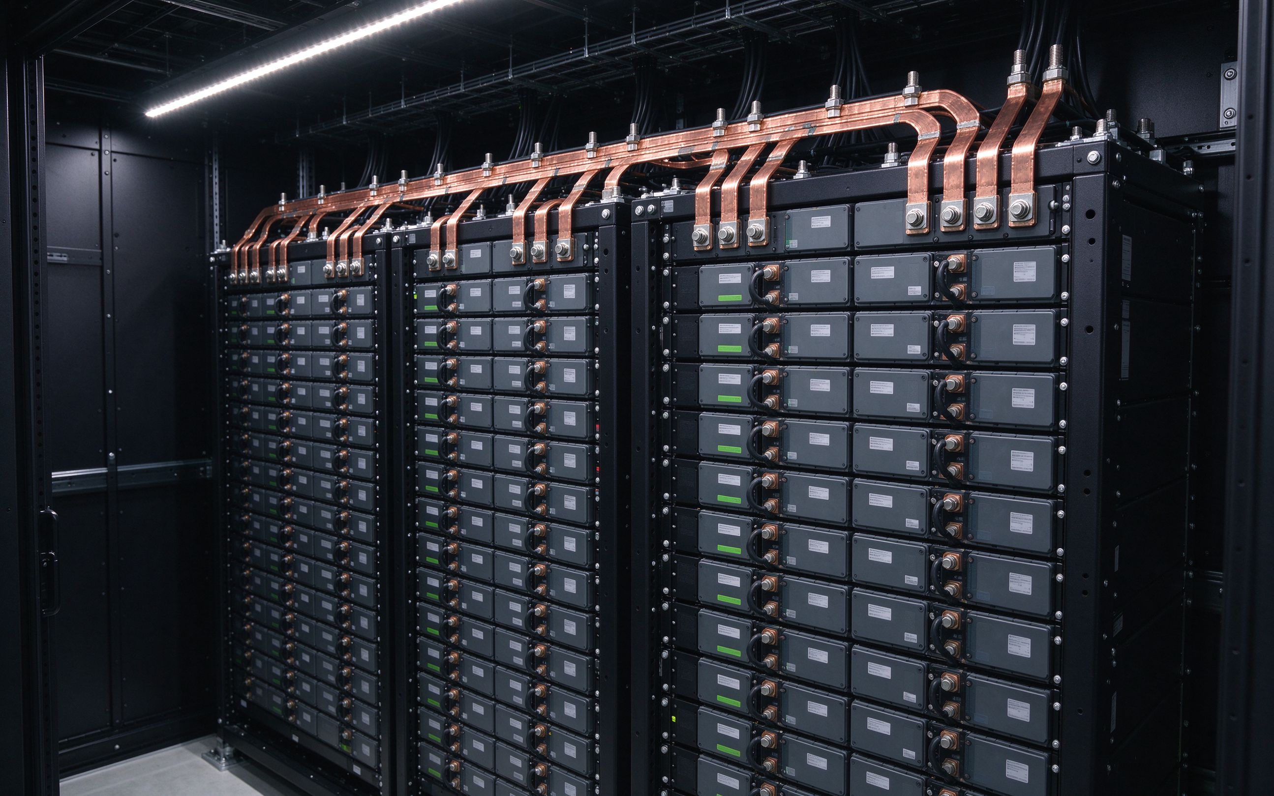
The economic case for busbar in data centers is straightforward at high currents. A cable run sized for 400 A continuous needs roughly 2-3 parallel bundles per phase, plus oversized neutral and ground. An equivalent laminated or rigid busbar assembly occupies a fraction of the volume, dissipates less heat per ampere, and allows tap-off units to be added without shutting down the row.
Laminated busbars, in particular, are useful at the transition points where phases and neutral need to be tightly bundled: between the UPS output, the row distribution unit, and the rack power shelf. The interleaved layers keep inductance low, which matters when the load is a bank of switching power supplies with fast transient response. For a broader discussion, see our busbar vs cable comparison.
| Distribution Element | Best For | Weakness |
|---|---|---|
| Under-floor cable bundles | <10 kW per rack, legacy halls | Heavy, slow to reconfigure |
| Overhead cable tray | Medium loads, mixed rows | Tap-off labor, bend radius |
| Rigid busway trunking | 200-800 A row feed | Less design flexibility at transitions |
| Laminated busbar assemblies | UPS-to-row, row-to-rack transitions, high di/dt loads | Custom geometry needed per site |
The reconfiguration argument is underrated. In a cloud hall, racks move between pod redesigns. With under-floor cables, every move is a physical re-pull: lift tiles, pull new bundles, re-terminate, re-test. With overhead busway plus tap-off units, a move is a 30-minute swap of a tap box. At the scale of a hundred racks, that flexibility has real economic value, independent of the electrical efficiency.
Inside the rack, the 12 V legacy distribution is giving way to 48 V DC, and in some hyperscale designs, to 400 V DC bus architectures. At 48 V, a 100 kW rack pulls over 2000 A inside the enclosure. Cables at that current are impractical; copper busbars, often laminated, are the only sensible path between the power shelf and the tray-level regulators.
The design considerations are familiar to anyone who has built an inverter busbar: low inductance for fast load transients, controlled impedance to avoid ringing, and robust thermal management. SHANYU builds rack-level laminated busbars using C11000 copper, tin-plated at terminals, with PET or Nomex dielectric depending on temperature. The 30°C ambient reference in our ampacity chart is the starting point; racks with forced front-to-back airflow should be derated with the integrator's thermal model.
Design note: at 48 V and kiloampere-class currents, even a 0.1 mΩ contact resistance drops 200 W of heat per connection. Plan torque sequences and plating (tin) carefully; read our terminal connection guide before locking the interface.
Transient response is the other reason laminated busbars win inside the rack. A GPU workload can step from idle to full power in tens of microseconds. The power shelf has to respond, and the busbar between shelf and trays has to carry that di/dt without ringing or voltage spikes. A laminated busbar's low loop inductance is exactly what keeps the rail stable during those transients.
Efficiency matters at rack scale. A 100 kW rack running at 97% efficiency loses 3 kW as heat. Halve the contact resistance from 0.1 mΩ to 0.05 mΩ at every joint, and you save hundreds of watts per rack. Multiply that across a thousand racks and you have saved megawatts of cooling load, which itself translates into fewer chillers, smaller switchgear, and lower PUE. The busbar, in other words, is not just a distribution part; it is part of the cooling equation. This is why hyperscale operators are increasingly specifying laminated busbars at the rack transition, not just at the UPS output.
Maintenance and safety are the other reasons the busbar approach wins. A bolted busbar joint can be inspected and torqued; a crimped cable lug in a crowded tray cannot. In a data center where uptime is everything, the ability to walk down a row and visually verify every connection has real value. Busway tap-off units also allow hot-swap adds: a new rack can be powered from an existing tap without de-energizing the row, which is the operational model that cloud operators need.
For the 2026 build cycle, we expect to see more 48 V DC rack power shelves, more overhead busway, and more custom laminated transition parts between the shelf and the tray regulators. The hall is not going back to under-floor cables. If you are specifying power distribution for a new AI hall, bring the busbar supplier in early — before the rack power shelf and the row distribution unit are finalized — so the transition parts are designed to fit rather than retrofitted. The cost of a last-minute busbar retrofit in a live data center is orders of magnitude higher than the cost of designing it in at the schematic stage. Bring the busbar supplier to the architecture review, not to the punch list. At SHANYU, we have been building laminated busbars for power electronics and UPS applications since 2012, and we ship internationally by sea and air from our Rizhao plant. We are happy to review your one-line diagram and rack power budget early in the design cycle. A custom busbar quote comes back within one working day, samples in 5-7 working days, and mass production in 2-3 weeks once drawings are frozen. Every SHANYU busbar ships with 100% hipot, insulation-resistance, and continuity test records, so incoming inspection is fast and documentation is complete. We work with UPS OEMs, power-shelf vendors, and data center builders across North America, Europe, and Asia, shipping by sea and air from Rizhao, Shandong. We support both pilot deployments and multi-hall rollouts with rolling forecasts. Every busbar is built to your drawing and tested 100% before it leaves our Rizhao plant, with full documentation shipped alongside for your internal quality records.
Data center reliability hinges on the ability to service a UPS without cutting the load. Maintenance bypass switches, static bypass switches, and isolation transformers all sit in series with the main distribution. Each one is a bolted joint where a laminated busbar assembly simplifies installation: a single drop-in part replaces a hand-built cable bundle, and every joint is tightened to a documented torque.
SHANYU works with UPS and power-shelf OEMs on custom busbar assemblies for these transition points. Our DFM-first process means we look at the whole envelope — the UPS footprint, the bypass switch terminals, the cable entry — before we quote. A custom busbar quote comes back within one working day, samples in 5-7 working days, and mass production in 2-3 weeks.
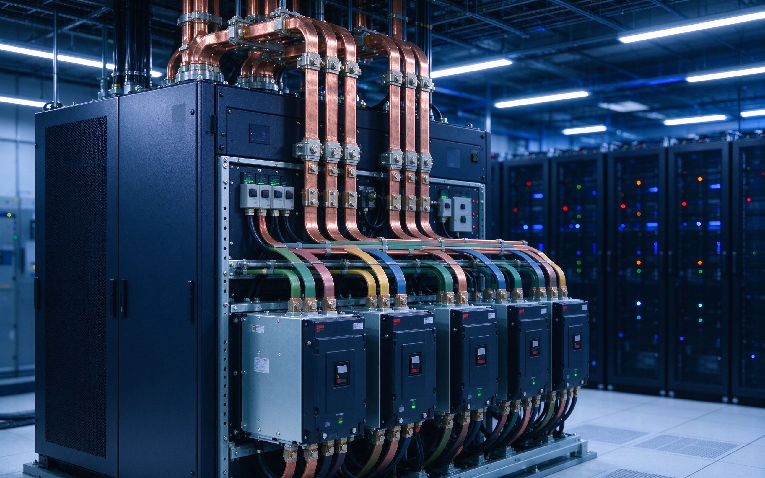
For the adjacent power-electronics context, cross-read our article on SiC/IGBT DC-link busbar design. Many of the same low-inductance principles apply to the inverter stages inside a modern UPS, which itself is increasingly a high-frequency SiC-based converter rather than a legacy line-interactive transformer.
Data center builders love standardization, but every hall is different. The practical pattern in 2026 is a hybrid: standard busway trunking from established vendors for the long row runs, plus custom laminated busbar assemblies for the transition points where two pieces of equipment mate. UPS to row distribution, row to rack power shelf, rack power shelf to tray regulators — these are the custom geometries where a good busbar supplier earns its keep.
When you buy laminated busbars for a data center program, look for a busbar OEM that can commit to: in-house lamination (not outsourced), full edge sealing, 100% electrical test (hipot, insulation resistance, continuity), and predictable lead times across a multi-year build. SHANYU has manufactured in Rizhao, Shandong since 2012, shipping internationally by sea and air. We do not subcontract the lamination step, because that is where the insulation and inductance quality is set.
For multi-hall programs, we recommend designing a small family of transition busbars that repeat across sites. A UPS-to-row part, a row-to-shelf part, and a shelf-to-tray part cover most of the hall. Standardizing those three geometries across your fleet reduces qualification effort and spares inventory. If you are planning a 2026 AI hall and want a second opinion on the busbar transition points, send us the one-line diagram and the rack power budget. We will come back with a geometry recommendation and a fixed-price budget through /contact/ or busbar@shanyo.com.
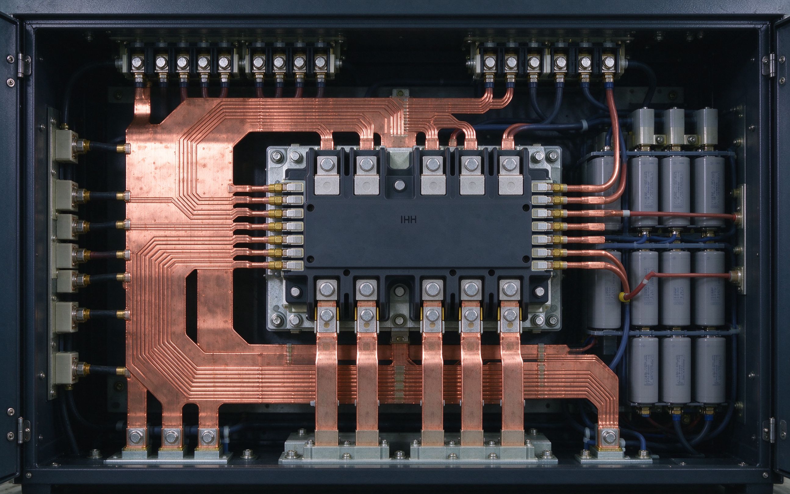
Higher switching speeds from SiC MOSFETs and modern IGBTs are pushing the DC-link busbar t
Read article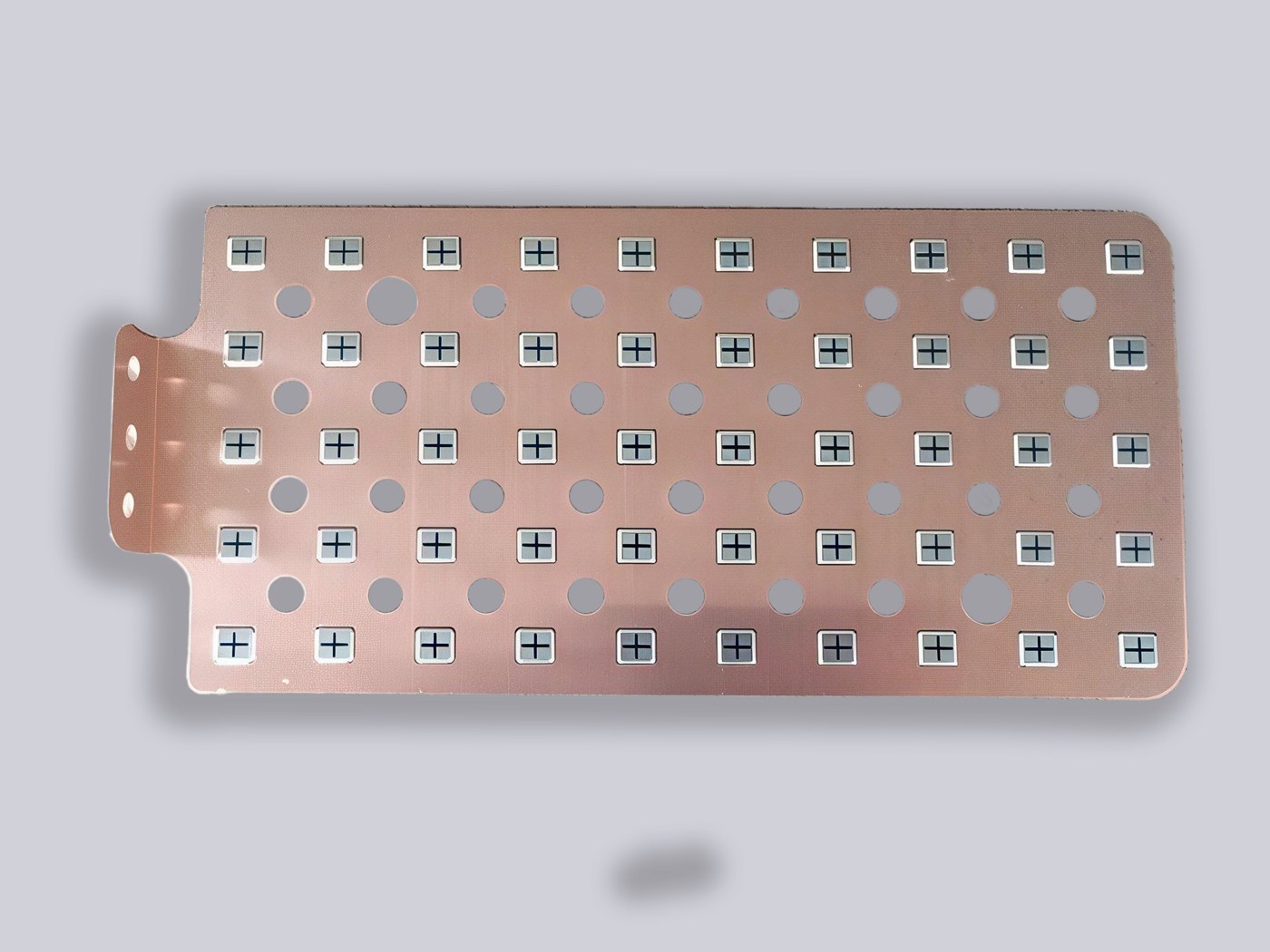
Copper busbar current rating is not a single number. It is a starting ampacity adjusted by
Read article
The terminal is where a laminated busbar meets the outside world. This guide covers M6/M8
Read articleSend the current profile, voltage class and terminal types — our engineers reply within one business day.
Send drawings, current ratings and voltage class — DFM feedback and a quotation within one business day.
