The lab-to-vehicle threshold has been crossed. In June 2026, Stellantis and Factorial announced the integration of Factorial's FEST solid-state technology into a Dodge Charger Daytona development vehicle and the start of a road-testing programme - the first solid-state cells in a Stellantis vehicle. In July 2026, BMW was testing its solid-state pack in an i7 prototype, keeping the production 400 V architecture and swapping only the module-level interconnects. For anyone who designs battery pack electrical architecture, the question is no longer whether solid-state arrives, but what it changes in the interconnect layer.
The lab-to-vehicle threshold has been crossed. In June 2026, Stellantis and Factorial announced the integration of Factorial's FEST solid-state technology into a Dodge Charger Daytona development vehicle and the start of a road-testing programme - the first solid-state cells in a Stellantis vehicle. In July 2026, BMW was testing its solid-state pack in an i7 prototype, keeping the production 400 V architecture and swapping only the module-level interconnects. For anyone who designs battery pack electrical architecture, the question is no longer whether solid-state arrives, but what it changes in the interconnect layer.
The BMW integration strategy is the most revealing datapoint. The prototype pack occupies identical mounting points as the production i7 battery, retains the same 400 V nominal bus voltage, and interfaces with the existing third-generation eDrive BMS through a CAN FD protocol extension - no new controller. Engineers replaced only the module-level interconnects and added localised pressure sensors inside each cell-stack enclosure (VehicPulse, July 2026). The message: solid-state adoption in the near term is a pack-integration exercise, not a platform redesign, and the electrical interconnect is one of the few components that changes.
Factorial's FEST solid-state cells in the Stellantis Charger use a patented mechanical architecture for cell-level containment, again pointing at the same engineering surface: how cells are held, pressed, sensed and interconnected (Factorial/Stellantis announcement, June 2026). The interconnect - busbars, welds, terminals - is where the new chemistry's requirements land first.
Two more datapoints put the transition in context. First, the BMW prototype's decision to keep the production BMS and add only sensing means the interconnect layer is being treated as the interchangeable part of the pack - the component that changes first and that the supply chain must be ready to re-engineer quickly. Second, the Stellantis-Factorial road-testing programme is explicitly a mechanical-architecture exercise: cell containment, pressure and the electrical interface are being validated together on the road, which is where vibration and thermal cycling evidence starts to accumulate for solid-state interconnects.
For suppliers, the pattern across both programs is that the cell chemistry is held constant while the integration changes. That favours suppliers who can move fast on module-level interconnect redesigns, who hold the weld and joint data from the first prototypes, and who can scale the documentation from prototype to production without a format change. The qualification question is no longer whether the chemistry works - it is whether the interconnect supply chain can follow the chemistry into the vehicle at automotive volume and automotive quality.
Solid-state chemistries change four pack-level variables versus today's lithium-ion. Operating temperature: several solid electrolytes prefer elevated temperature, shifting the thermal management paradigm from cooling to conditioning. Mechanical behaviour: solid-state cells 'breathe' differently - less swelling in some chemistries, more load-path sensitivity in others - so the interconnect must survive dimensional movement without fatigue. Pressure sensitivity: cell performance and life depend on stack pressure, which means the electrical layer must coexist with a mechanical clamping system. And, in the near term, current capability: demonstration packs are being built with conservative C-rates while the chemistry matures.
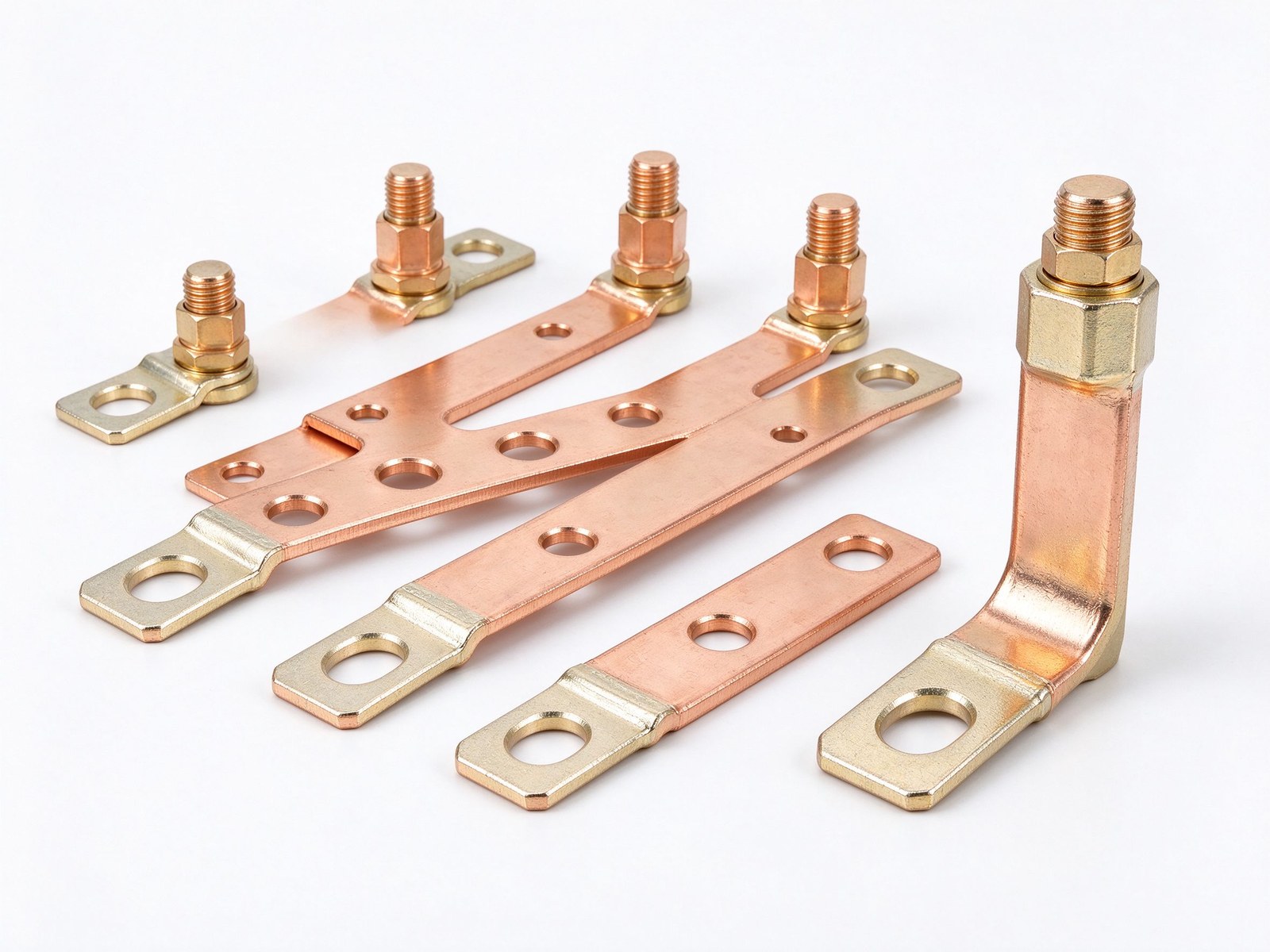
Every one of those variables touches the busbar between cells and modules.
BMW kept 400 V; many new programs are 800 V. The platform decision is unchanged by the electrolyte chemistry. What changes is the current path. Semi-solid packs running sustained 1-3 C discharge into an 800 V architecture target joint resistance below 0.15 mΩ per busbar connection, verified with four-wire Kelvin measurement on 100% of production joints (Horizon Power, August 2026). That is a manufacturing and inspection target, not just a design target.
At pack level, the same hierarchy applies as in a conventional pack: primary busbars interconnect cell terminals into modules, secondary busbars interconnect modules into the pack (MDPI review, July 2026). The difference is the failure mode tolerance: solid-state packs are being specified with tighter resistance budgets and more rigorous weld and joint inspection because the pack is less tolerant of a hot joint when operating windows are narrower.
Jumai's engineering analysis puts it bluntly: to accommodate the mechanical 'breathing' of solid-state packs without tearing terminals apart, flexible laminated copper busbars and braided copper connectors transition from specialised components to mandatory requirements for every cell-to-cell connection (Jumai Hardware Technology, March 2026). The logic is mechanical: a rigid bar couples cell movement directly into the weld or bolt; a flexible laminated connector absorbs the movement, keeping the joint interface stress low.
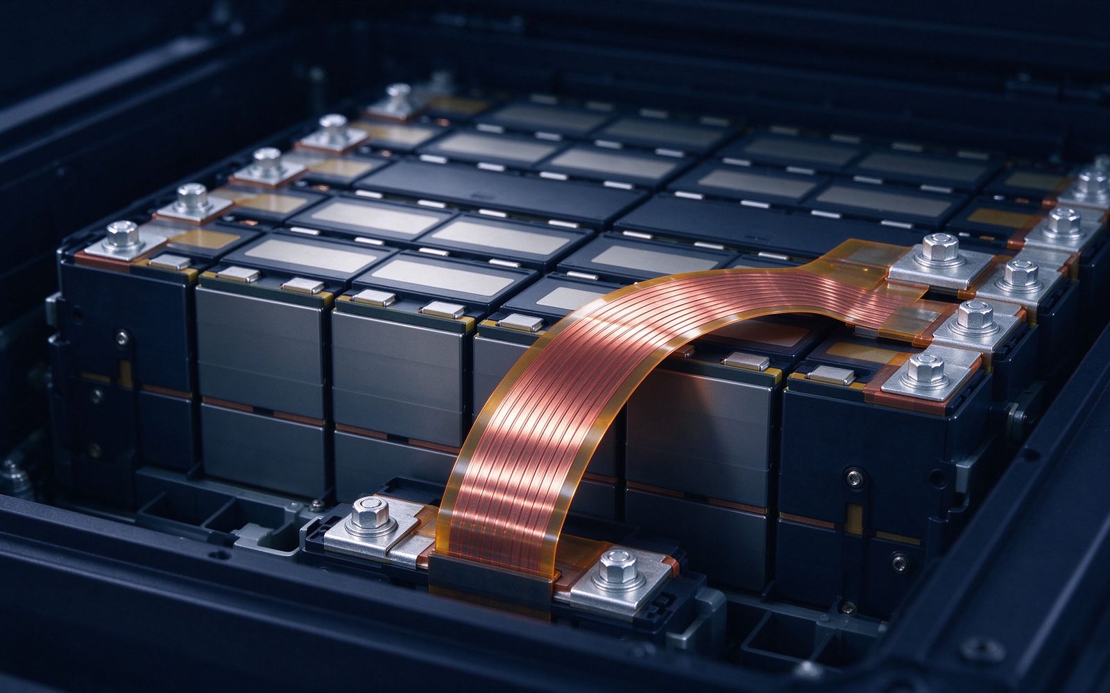
SHANYUAN builds both rigid laminated stacks and flexible insulated busbars, so the rigid-vs-flexible decision can be made per connection rather than forced once for the whole pack.
At the tab-to-busbar interface, ultrasonic welding is preferred on semi-solid programs because it avoids the heat-affected zone that laser or resistance welding introduces into a pressure-sensitive cell environment (Horizon Power, 2026). Ultrasonic welds create a solid-state joint below the melting point, which preserves plating and minimises distortion. The trade-off is joint-area limits: ultrasonic weld heads bound the practical weld area, so large cross-sections need multiple weld spots or a hybrid approach.
Laser welding returns at module and pack level where joint geometry is accessible and heat can be managed. The right choice depends on cell format, tab material (copper, aluminium, or nickel-plated) and the pack's pressure budget - a decision our engineering desk supports with welding and joining guidance built from production practice.
Solid-state cell performance depends on stack pressure, and the clamping system that applies it now sits on top of the electrical interconnect. Two consequences follow. First, the busbar footprint must leave room for pressure-distribution plates and sensing; second, bolted busbar-to-module connections must hold their preload while the pack is compressed and while it thermally cycles.
The design rules for bolted connections - preload, Belleville washers, thermal-cycle fatigue - become pack-level engineering rather than hardware selection. The bus-to-bus connection guide covers the bolted joint practice, and our guide on vibration and bolted joint design adds the mechanical rules for a pressure-clamped pack environment.
The pressure requirement has a second-order effect on the busbar that is easy to miss: the clamping system occupies space and adds mass, and the busbar footprint must share the cell-stack envelope with it. A pack layout that was designed around a rigid, full-width busbar may need to move to a segmented or flexible interconnect simply to leave room for the pressure plate and its sensors. This is why the mechanical and electrical layouts are now designed together rather than sequentially - the busbar drawing and the pressure-plate drawing are the same drawing in a solid-state program.
The sensing layer reinforces the point. Localised pressure sensors, as added in the BMW prototype, need mounting space, wiring paths and electrical isolation from the busbar. A laminated busbar with integrated sense taps can host the temperature sensing on the conductor plane itself, while the pressure sensors mount on the mechanical structure - a clean separation of electrical and mechanical sensing that simplifies the BMS wiring and the assembly sequence.
Some solid-state chemistries operate most efficiently at elevated temperature, which flips the thermal problem from 'keep it cool' to 'keep it in the window'. The busbar's thermal role changes accordingly: instead of maximising heat rejection, the pack wants a predictable, low-temperature-gradient current path whose losses are known and whose heat can be steered toward the pack's thermal-conditioning system.
Laminated construction helps here because the flat laminate face couples to the conditioning plate across a large, predictable area. The same geometry that rejects heat in a conventional pack becomes a controlled thermal interface in a solid-state pack.
BMW's prototype added localised pressure sensors inside cell stacks and BMW's pack retained the production BMS with a CAN FD extension. That pattern - keep the controller, add sensing - puts the interconnect layer in the sensing loop. Busbar-mounted temperature sensing is straightforward; pressure sensing requires the mechanical design to allocate space and mounting for sensors at cell-stack level.
For SHANYUAN's part, BMS busbars with integrated sense taps are a standard product family, so the sense path is designed into the laminate rather than added as field wiring.
The 0.15 mΩ-per-joint target with Kelvin four-wire verification on 100% of joints is a manufacturing commitment. It changes how busbar suppliers work: plating thickness becomes a lot-controlled variable (tin, silver, nickel), weld parameters are captured per joint, and electrical resistance is measured at the joint, not inferred from material conductivity. Inspection records become part of the pack's quality file.
SHANYUAN's factory is set up for this: dimensional inspection, plating checks and pull-out testing on terminals, with records that support PPAP-style submissions from battery OEMs.
Verified Market Reports sizes the copper busbar for EV battery and inverter market with solid-state adoption as an explicit growth driver, noting that larger battery modules and rising current flow require busbars with enhanced cross-section and thermal management capability (Verified Market Reports, May 2026). As cell formats grow and pack voltage rises, the copper content per pack trends upward even before chemistry changes - solid-state accelerates the shift toward thinner, higher-surface-area laminate stacks.
Five questions decide whether a busbar partner is ready for solid-state programs: Can you document joint resistance on production parts (not prototypes)? Can you build both rigid and flexible laminated interconnects? Do you size for a pressure-clamped pack environment, including bolted-joint preload and thermal cycling? Can you integrate sense taps for temperature and pressure instrumentation? And can you support PPAP-style documentation and bilingual FAT records? If the answer to any of these is a shrug, the supplier is not ready.
For pack programs with solid-state on the roadmap, the practical move is to freeze the electrical architecture now and qualify the interconnect at the same drawing-and-prototype pace used for current chemistries. The 400 V / 800 V platform, the module layout and the terminal pitch are the variables that will not change with the electrolyte; the interconnect is where the change lands. Send your module layout and current profile to SHANYUAN's engineering desk and we will size the interconnect - rigid, flexible or a mix - against the pressure and temperature envelope of the pack. Start with our battery busbars page or the EV application page.
Cell format drives interconnect geometry. Pouch cells present wide, thin tabs that favour flexible laminated connectors or braided straps; prismatic cells present terminal posts that favour rigid busbars with bolted or welded interfaces; cylindrical cells in large formats are moving toward busbars that combine weld pads and sense taps in one stamping. Solid-state programs are so far following the host cell format, which means the interconnect supply chain must be ready for all three at once.
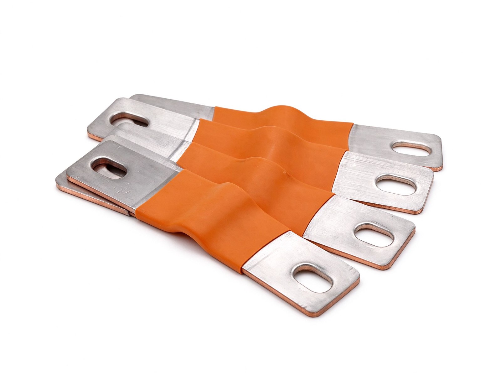
The lesson for pack teams is to freeze the cell format before freezing the interconnect: the busbar design, the welding process and the inspection plan all inherit the format decision. Our dual-layer cell interconnect busbar family shows the geometry options for module-level interconnects, and the impedance simulation guide shows how the interconnect layout is validated before prototypes are welded.
Solid-state packs do not change the fundamental creepage and clearance rules, but they do change the operating envelope in which those rules must hold. If the pack runs hot for optimal electrolyte conductivity, the ambient for the creepage calculation rises; if the pack is pressure-clamped, the busbar edges sit under mechanical load, and creepage along the laminate edge becomes a mechanical-thermal-electrical coupled problem.
The design response is the same practice we apply on every laminated part: dielectric and edge-sealing selected for the voltage class, creepage distances sized with margin, and terminal spacing fixed so that installation cannot reduce the distances. The creepage and clearance design guide documents the sizing method in detail.
Solid-state chemistries are being pitched partly on faster charging - higher C-rates without the thermal runaway risk of liquid electrolytes. For the interconnect, higher C-rate means higher pulse current through the same cross-section, which raises two requirements: the joint resistance budget tightens (I2R at 3 C is nine times the loss at 1 C), and the thermal path must handle the pulse without creeping past the pack's temperature window.
A laminated busbar with a bonded cold plate answers both: the flat laminate couples the pulse heat to the conditioning plate quickly, and the documented rise calculation at the program's worst-case C-rate becomes part of the pack's safety case. The thermal design method is covered in our thermal management design guide.
Qualification of a solid-state pack interconnect follows a familiar sequence with tighter gates: first-article dimensional and plating reports, joint-resistance measurement on prototypes, thermal-cycle and vibration testing at the pack's envelope, welding-process qualification for the tab interface, and PPAP-style documentation for production. The difference from conventional packs is the pressure dimension: the interconnect test plan must include the clamped condition, not free-standing.
Suppliers that already hold rail or automotive documentation discipline - inspection records, lot traceability, bilingual reports - are the ones that clear these gates without a second round. The practical advice: engage the busbar supplier at the cell-format decision, not after the pack layout is frozen.
Battery OEMs qualify suppliers with a documentation chain that solid-state programs will inherit and tighten: material certificates for the copper and the dielectric, plating thickness records per lot, dimensional reports per first article, weld or joint resistance measurements per unit, and the pack-level test evidence for the interconnect. Solid-state programs add the pressure dimension to the file - the clamping scheme, the pressure test record and the joint behaviour under the clamped condition.
For the supplier, the practical implication is that the documentation system is part of the manufacturing system. Records must be generated per part, not reconstructed after the fact, and the batch traceability must survive the vehicle's life. Suppliers already running this discipline for automotive programs - dimensional, plating and pull-out inspection on every batch - are the ones that clear a solid-state audit without rework. The same evidence chain is described on our quality page.
The documentation chain also has a cost dimension that pack programs under-estimate: the interconnect file follows the vehicle. A battery pack in service for a decade is inspected, maintained and eventually recycled; the busbar records - material certs, plating lots, weld data, joint resistance values - must survive that whole life in a form the maintainer and the recycler can use. Suppliers that build the record per part, with batch traceability, give the pack owner an asset rather than a liability, and that asset becomes part of the pack's residual-value argument in the fleet economics.
The interconnect layer is a small share of pack cost and a large share of pack risk, which is exactly why its cost structure matters. Copper content follows the current path and the laminate geometry; plating is a process cost that grows with surface area; the welding or bolting process adds equipment and inspection cost; and the documentation adds overhead that scales with lot traceability requirements. In solid-state programs, the flexible-connector share of the interconnect tends to rise - flexible laminated or braided connectors cost more per ampere than rigid bars, but they buy the mechanical survival that a rigid bar cannot guarantee.
The budgeting lesson for pack teams: do not optimise the interconnect on unit cost alone. A joint that saves a dollar and costs a warranty return is not a saving; the target is the documented, inspected joint whose resistance and mechanical behaviour are repeatable. That is the same reasoning behind specifying flexible insulated busbars where the pack breathes.
Send the current profile, voltage class and terminal types — our engineers reply within one business day.
