A busbar, a bus duct and a cable all conduct current — but they solve different problems. A busbar distributes power inside equipment, a bus duct routes it across a building, and a cable does both where flexibility matters more than density. Engineers often blur the three terms in specifications; this guide draws the line, gives the decision table, and shows where a laminated busbar replaces either of the other two.
A busbar, a bus duct and a cable all conduct current — but they solve different problems. A busbar distributes power inside equipment, a bus duct routes it across a building, and a cable does both where flexibility matters more than density. Engineers often blur the three terms in specifications; this guide draws the line, gives the decision table, and shows where a laminated busbar replaces either of the other two.
A busbar is a rigid bar or laminated stack of copper (or aluminum) that distributes current between components inside a panel, inverter, battery rack or switchgear assembly. A bus duct (also called busway or busbar trunking) is a factory-built enclosure that carries one or more busbars along a route — up a building riser, across a factory floor or over a data-center hall — with tap-off points where loads connect. A cable is a flexible round conductor that routes power point-to-point, around obstacles, over long distances.
The practical distinction is scale and length: a busbar is measured in centimeters and works at component level; a bus duct is measured in meters and works at distribution level; a cable spans both but trades current density for flexibility. If you are new to the terms, our what is a busbar explainer covers the component-level picture first.
The most common specification error is using “busbar” and “bus duct” interchangeably. They are different products at different points of the distribution chain:
| Dimension | Busbar (bare or laminated) | Bus duct / busway |
|---|---|---|
| Typical length | Centimeters to ~1 m, inside equipment | Meters to tens of meters, between equipment |
| Job | Connect components: cells, modules, IGBTs, capacitor banks | Route bulk power from transformer/switchgear to loads or floors |
| Enclosure | Sits inside the equipment enclosure | Own protective housing with IP rating and fire barriers |
| Tap-offs | Bolted or welded joints per drawing | Plug-in boxes / pre-engineered tap-off openings |
| Typical standard | IEC 61439 assembly, UL 891 switchboard | IEC 61439-6 busbar trunking, UL 857 busways |
In short: you specify a bus duct when the question is “how does power travel across this building?” and a busbar when the question is “how do components inside this equipment share power?”
Inside equipment, busbars beat cables on three measurable axes: inductance (a flat laminate cancels loop area), thermal surface (a wide bar radiates heat better than a round conductor of the same cross-section) and packing density (bars bolt directly to terminals with no bend radius). The crossover is typically in the 50–200 A per phase range inside a confined volume — below that, cable terminations are usually cheaper; above it, the bar wins on loss, temperature and space. Our busbar vs cable comparison quantifies the impedance and thermal numbers, and the busbar vs cable harness selection guide walks a real selection.
For a switching circuit — an inverter, a DC-link, a battery pack — the deciding factor is usually loop inductance, not raw current. A long cable pair has large loop area; a laminated busbar has a near-zero loop because the layers are separated by microns of dielectric. That is why EV traction, BESS racks and solar inverters standardize on laminated busbars rather than cables for the high-frequency paths.
A bus duct earns its cost in four situations:
The common thread is reconfiguration: bus duct pays for itself when loads move. If loads are fixed and the route is short, a simple cable tray or a laminated busbar inside the assembly is usually the lower-cost answer.
Cable remains the right answer for: long runs beyond a few meters where no duct is justified; complex routing around beams, through conduits and into tight equipment; vibration and relative movement between machines; and low currents where termination costs dominate. A cable also wins on install flexibility — it can be pulled, re-routed and re-terminated on site with hand tools, while bus duct and rigid busbars are factory-built to a layout.
Do not assume cable is always cheaper: for 400 A and up over a few meters, the cable itself, the glanding, the group derating and the larger containment can cost more than an engineered busbar. The busbar connections reference explains the joint designs that make bolted bar systems reliable at those levels.
| Scenario | Typical choice | Why |
|---|---|---|
| IGBT / SiC inverter DC-link | Laminated busbar | Low inductance, blade terminals |
| EV battery pack interconnect | Laminated busbar | Vibration, compact, low loss |
| BESS rack-to-rack / rack-to-converter | Laminated or flexible busbar | Low-resistance joints, hot-swap |
| Switchboard internal distribution | Rigid copper busbar | Standard practice, cheap to tap |
| Transformer to main switchboard | Bus duct | Bulk power, short route, reconfigurable |
| Multi-floor building riser | Bus duct / busway | Shaft space, tap-offs per floor |
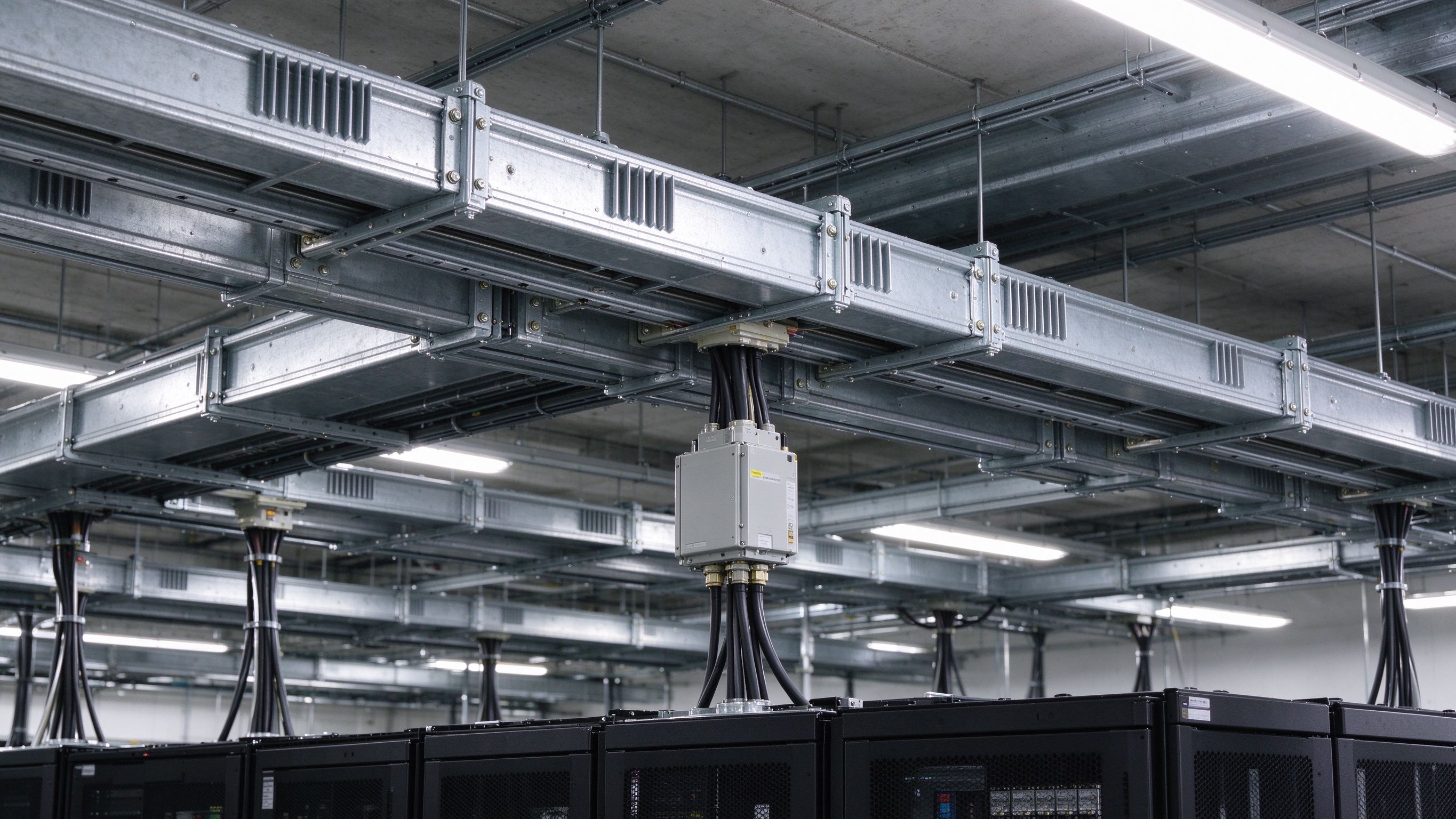
| Data-center overhead feed | Plug-in busway | Move racks without recabling |
| Long run, complex routing, low current | Cable | Flexibility and install ease |
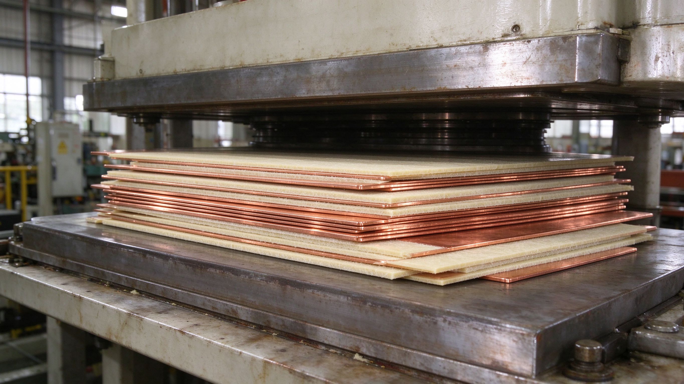
Where the decision lands on a busbar, the laminated construction usually beats a bare flat bar inside power electronics: the dielectric layers (PET, Nomex or epoxy DLF) between copper layers cut loop inductance, and the stack integrates terminals, sense taps and mounting points in one part. Our multi-layer insulated busbar covers 1–6+ conductor layers up to roughly 1000 A at a 30 °C rise; the EV inverter laminated busbar and capacitor bank busbar pages show the DC-link and bank variants.
If your project is currently a cable harness inside a panel, the harness-to-busbar selection guide gives the conversion criteria. If it is a bus duct question at the component boundary, the transition is usually a short laminated bar with a bolted interface to the duct.
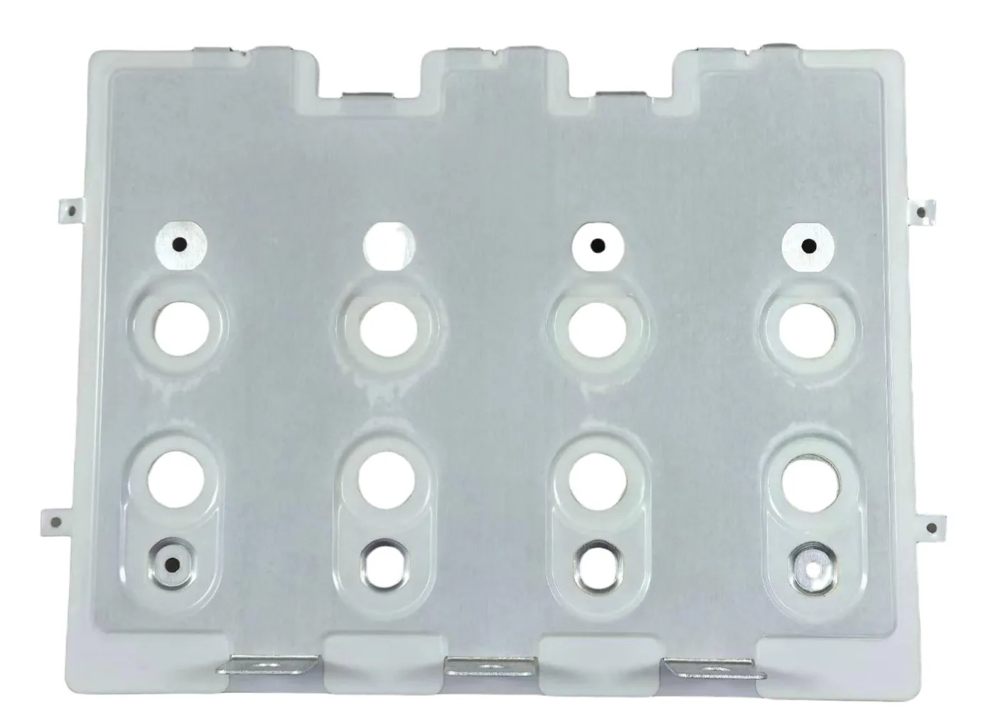
Whatever the conductor, the usable current is set by temperature rise, not cross-section alone. A busbar sized in free air will run hotter inside a sealed enclosure; a bus duct sized at one ambient must be derated in a hot room; cables in a bundle derate by group factor. The busbar ampacity calculator estimates copper and aluminum capacity with mounting and ambient inputs, and the ampacity chart gives cross-section-by-cross-section reference values at 30 °C rise. The full method — including the ΔT = (I/K)²/A formula and IEC 61439-1 versus UL 891 limits — is in the ampacity calculation guide.
A useful planning rule for laminated stacks: around 1.2–2.0 A/mm² of copper under natural convection, derating as the enclosure warms. Always verify the final number against the actual enclosure and cooling before you send the drawing — the custom design route documents the calculation with your quotation.
Comparing cost per meter is misleading; compare installed cost per amp per meter with the failure and maintenance profile:
For a purchasing view — copper price exposure, lead time and how to evaluate supplier quotes — see the RFQ and supplier evaluation guide.
When the internal distribution is a laminated busbar, the terminal and connection guide covers the joint designs that keep resistance low and repeatable.
Is a bus duct the same as a busbar? No. A busbar is a conductor inside equipment; a bus duct is an enclosed system that routes one or more busbars across distances with tap-offs. They are tested to different clauses of IEC 61439.
Can a laminated busbar replace a bus duct? Only at the component boundary, not for long routes. A laminate replaces internal harnesses and connects equipment to the duct; the duct still carries bulk power across the building.
At what current should I switch from cable to busbar? Roughly 50–200 A per phase inside a confined volume, depending on length, enclosure and frequency. Above ~400 A per phase over a few meters, an engineered bar is usually cheaper and cooler than a cable group.
What is the price difference? Material cost favors cable at small sizes; installed cost per amp favors busbar and duct as current and reconfiguration needs rise. Send the current profile and layout to SHANYUAN engineering for a documented comparison.
At high current, busbars carry more amps per cross-section, cut parasitic inductance by an
Read article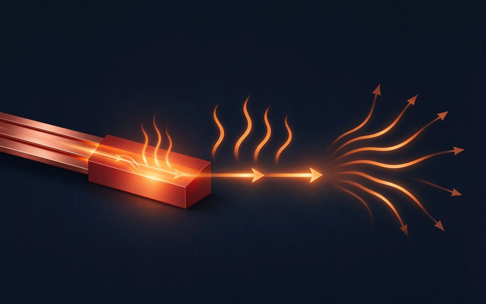
A busbar's rating is not a lookup — it is a calculation. Temperature rise is the real limi
Read article
The terminal is where a laminated busbar meets the outside world. This guide covers M6/M8
Read articleSend the current profile, voltage class and terminal types — our engineers reply within one business day.
