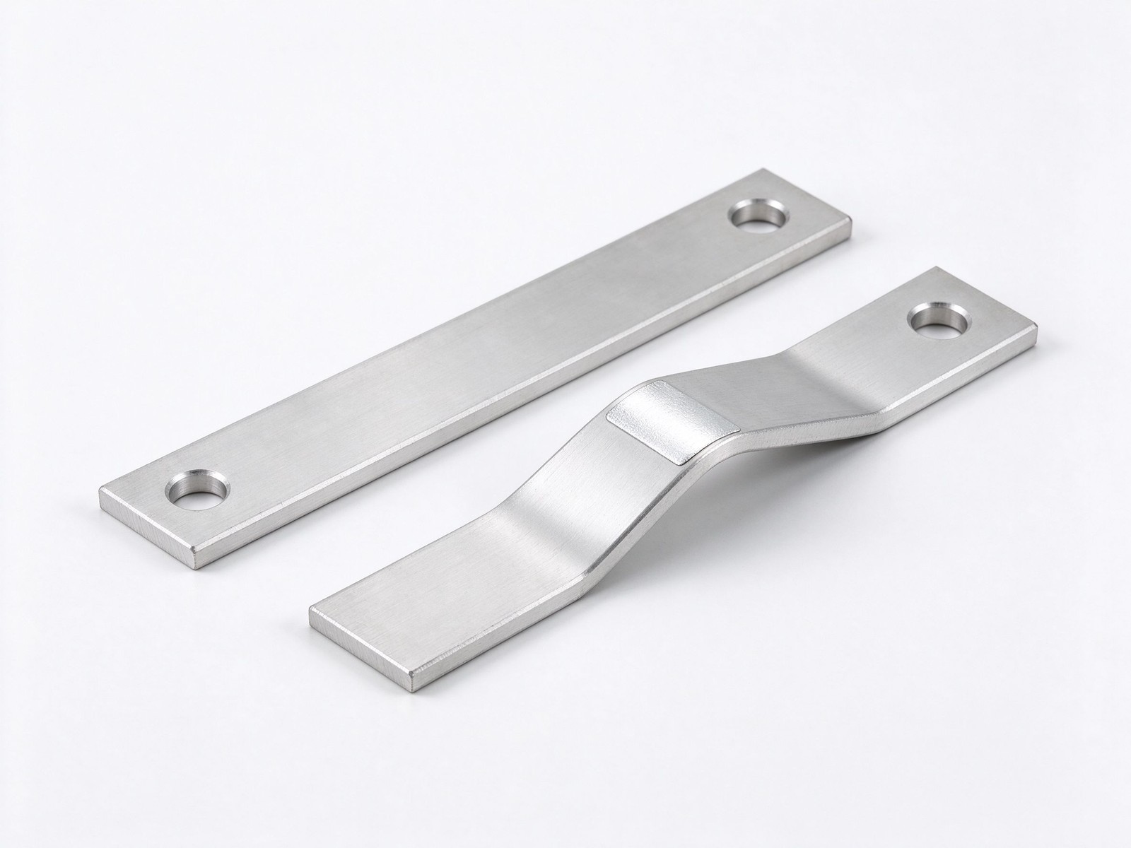
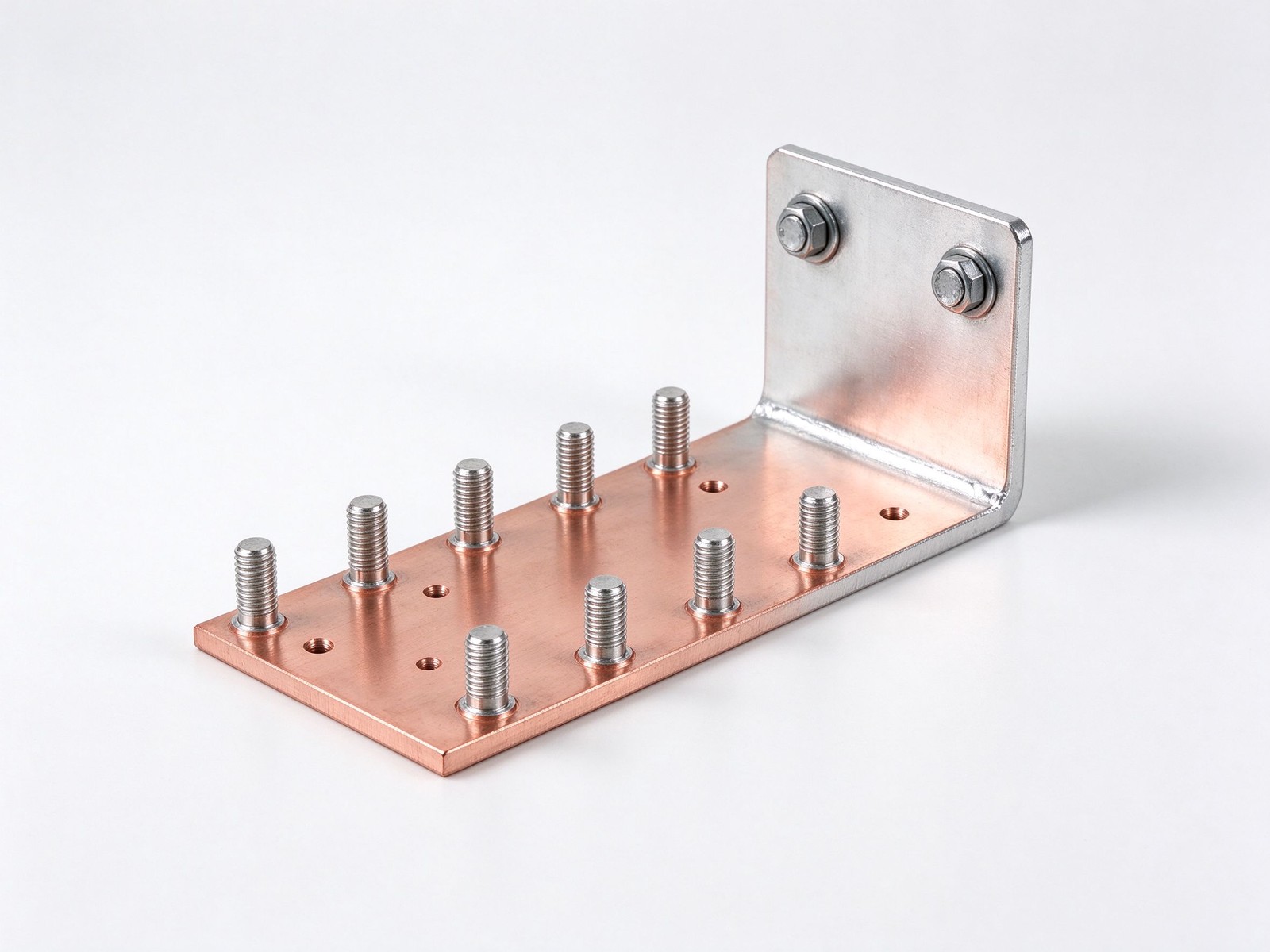
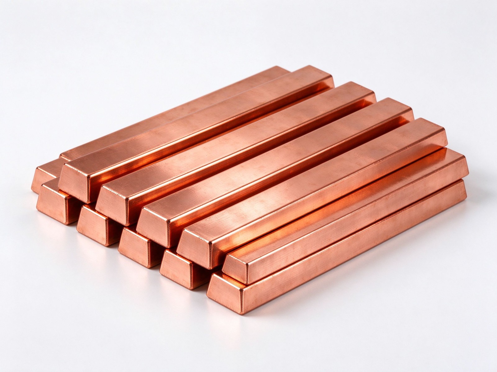
Your material guide to the electrical busbar family - copper and aluminium alloys, tempers and finishes, fabricated from your drawing.
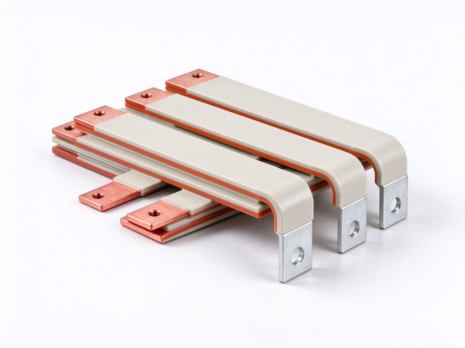
Product imagery: factory photo plus studio renders. The exact geometry, layers and terminals of your part follow your drawing.
Final values follow your drawing — this is the standard configuration of the family.
| Parameter | Value |
|---|---|
| Conductor alloys | C11000 ETP copper standard; C10100 OFHC, C14500 tellurium, C360 brass options |
| Aluminium grades | 6101, 6061, 6063, 1350, 1100 electrical and structural alloys |
| Conductivity range | C11000 at least 100% IACS; 6101 aluminium 57-61% IACS |
| Tempers | Annealed O-temper; half-hard H01-H04 cold-worked; hard temper for machining |
| Finishes | Bare, tin, nickel, silver plating; epoxy powder coat option |
| Formats | Solid bar, bent tabs, laminated stack, layered flexible bar |
| Fabrication | CNC punch, bend, laser, water-jet; DFM review before tooling |
| SKU | SY-CM-314 |
Key characteristics of this product family.
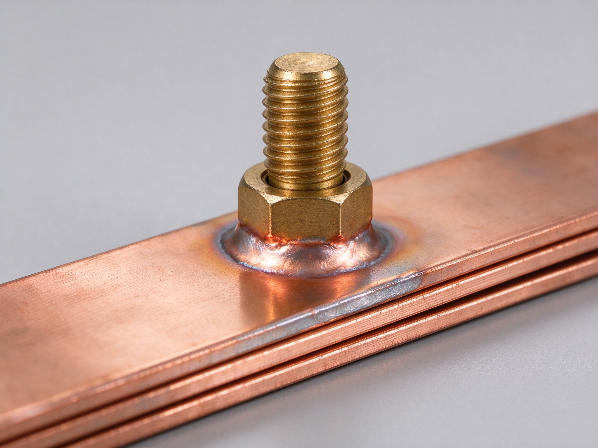
An electrical busbar is the conductor that collects power at one point and distributes it to many circuits - a rigid or layered bar in copper or aluminium that replaces a bundle of cables inside switchgear, panels and machines. It does two jobs at once: carry current, and do it in far less space than cable can.
Engineers choose busbar over cable for the lifetime gains. The bar runs cooler for the same current because its flat section gives a broad heat-radiating surface, voltage drop is predictable, inductance stays low, and there are no crimped lugs to loosen. Reconfiguration is a change of hole pattern, not a rewire - which is why panels built on busbar are faster to upgrade and cheaper to maintain over decades of service.
Material choice is where most design effort goes. Silver, copper, gold and aluminium are the most conductive metals; copper and aluminium dominate on cost and weight, and high electrical conductivity always pairs with high thermal conductivity. The alloy grade then trades conductivity against tensile strength, hardness and machinability: nothing is free, and the right grade depends on whether the bar is bent, punched, milled or left as stock.
SHANYUAN builds electrical busbars custom from your drawing. C11000 copper is our standard conductor, with electrical-grade aluminium as the weight-saving alternative; fabrication is fully CNC, plating and epoxy powder coating are done in-house, and every drawing goes through a DFM review before tooling. Engineering answers return within one business day.
The alloy grade sets the trade between conductivity and shop behaviour. C11000 electrolytic tough pitch copper is 99.9 percent pure and carries at least 100 percent IACS - the default for busbar - but it machines gummy and wears tooling, so feeds are slowed. C10100 oxygen-free copper reaches about 101 percent IACS and is chosen when brazing, soldering or butt-welding is on the drawing. C12200 solders easily at a conductivity penalty; C14500 tellurium copper keeps near-pure conductivity while machining like free-cutting stock; C360 brass is the most machinable copper alloy of all.
Stock lengths start from our copper bar stock range, and the trade-off maths is in copper versus aluminium.
Commercially pure 1100 and 1350 aluminium sit at 50 to 61 percent IACS, with 1100 the stronger of the two; the 6000-series structural grades weld well - 6061 near 40 percent IACS, 6063 near 50 - and 6101 is the standard electrical grade at 57 to 61 percent. Aluminium conducts about 61 percent of copper per unit area at less than a third of the weight, close to twice the conductivity per pound. Tempers matter: soft O-temper bends to tight radii, the half-hard H01-H04 range is the default for rectangular busbar, and hard temper suits machining but not bending. See the aluminium busbar range.
Where joints absorb vibration, thermal growth or mounting misalignment, a high-current flexible busbar stacks thin conductive layers and welds the ends solid - no separate lugs - carrying more current per section and shedding heat better than a solid bar. For irregular or one-off shapes, epoxy powder coating is applied after every bend, punch and mill, so the insulation stays uniform where shrink tubing or dip coating cannot. Both routes start from custom busbar design from your drawing with a DFM review before tooling.
Choosing the conductor alloy is the first real decision on any electrical busbar drawing. The cross-reference below packs the five grades our shops actually cut - the busbar conductor material guide we hand to engineers in the first meeting - with the typical published numbers that sizing and joint design hang on.
| Conductor Grade | Temper We Ship | Typical Conductivity | Density | Typical Tensile Range | Where It Earns Its Keep |
|---|---|---|---|---|---|
| C11000 ETP copper | Half-hard H04 | 100% IACS | 8.89 g/cm3 | 240-330 MPa | Distribution and switchgear bars, the everyday default |
| C10100 oxygen-free copper | Annealed soft | 101% IACS | 8.94 g/cm3 | 220-260 MPa | Brazed or butt-welded assemblies where oxygen-free metal matters |
| C14500 tellurium copper | Half-hard | approx 90% IACS | 8.94 g/cm3 | 260-360 MPa | Milled, threaded and high-volume machined terminals |
| C12200 DHP copper | Soft annealed | approx 85% IACS | 8.94 g/cm3 | 200-260 MPa | Easily soldered, piping-style or bent conductors |
| 6101-T6 aluminium | Extruded T6 | 57-61% IACS | 2.70 g/cm3 | 195-220 MPa | Weight-sensitive distribution runs, the 6101 aluminium busbar alloy |
The C11000 C10100 busbar copper alloy split is about process, not rating: C11000 stays cheaper and stiffer for cut-and-drill work, while C10100 remains sound through brazing heat. The grade choice rarely changes the joint hardware, but it does shift the bending allowance: half-hard C11000 and C14500 hold tighter radii than annealed OFHC, which flows and stretches under clamp pressure. Values in the table are typical published figures; confirm the exact temper against your DFM drawing before releasing tooling. The wider conductivity-versus-weight trade is explained in our copper versus aluminium notes, and once the grade is chosen the next step is sizing, and that pass starts by reading the ampacity chart.
Once the alloy is settled, sizing an electrical busbar is a three-pass job rather than a single lookup. The flow below is the same one our engineers run in the DFM meeting, with a conversion table that sketches the first pass in millimetres.
| Target Continuous Rating | Suggested C11000 Copper Section | Same-Rise 6101 Aluminium Section | Planning Note |
|---|---|---|---|
| approx 150 A | 15 x 3 mm (45 mm2) | 19 x 3 mm | Control and auxiliary circuits |
| approx 350 A | 30 x 5 mm (150 mm2) | 38 x 5 mm | Feeder bars in light panels |
| approx 700 A | 50 x 5 mm (250 mm2) | 64 x 5 mm | Main switchboard feeders |
| approx 1,200 A | 80 x 8 mm (640 mm2) | 102 x 8 mm | Transformer secondary risers |
| approx 1,800 A | 100 x 10 mm (1,000 mm2) | 127 x 10 mm | Parallel-bar builds, check supports |
The aluminium column applies the same width-first rule we use elsewhere: extra width beats extra thickness because it also doubles the radiating face. Parallel runs share heat, so trim each bar's independent rating by a small planning margin before cutting. These rows are planning estimates, not rated values; the final section is locked against your enclosure, supports and joint layout in the DFM review. Panel builders who want the background read what a busbar does inside a switchboard.
Where this busbar configuration earns its place.
Where this busbar configuration earns its place.
Where this busbar configuration earns its place.
Where this busbar configuration earns its place.
Where this busbar configuration earns its place.
Where this busbar configuration earns its place.
Your drawings reach the engineers who build the part.
Design risks flagged when changes are cheap.
Test records per lot, CoC and PPAP on request.
Drawing to delivered production parts, one supplier.
From spec review to shipped, tested parts — one accountable supplier.
Straight answers from the engineering team.
Every SHANYUAN busbar is custom, but the power circuits they connect recur across markets. Three typical ones — send us yours and we will point to the right stack-up.
Tight, low-inductance links between the battery source and traction inverters, fully edge-sealed for 400–800 V platforms.
Commutation-loop connections from DC-link capacitors to IGBT bridges, designed against switching overshoot V = L × di/dt.
Converter DC links built for rising bus voltages toward 1500 VDC, with creepage and partial-discharge margins included.
Construction, dielectric selection and current capacity basics.
Read the busbar design guideLayers, terminals, dielectrics and mounting are all configurable. Send us your spec for DFM review and a quotation within one business day.