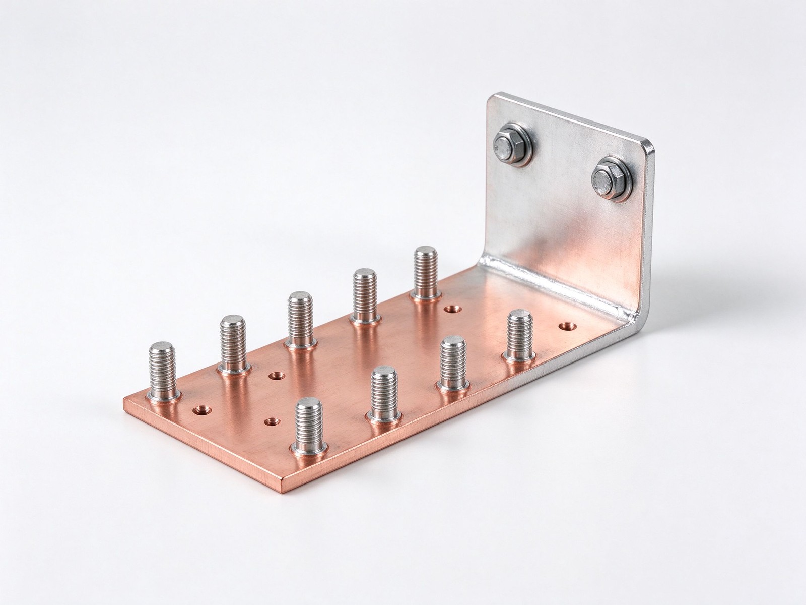
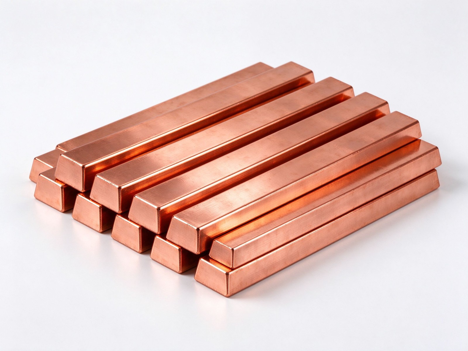
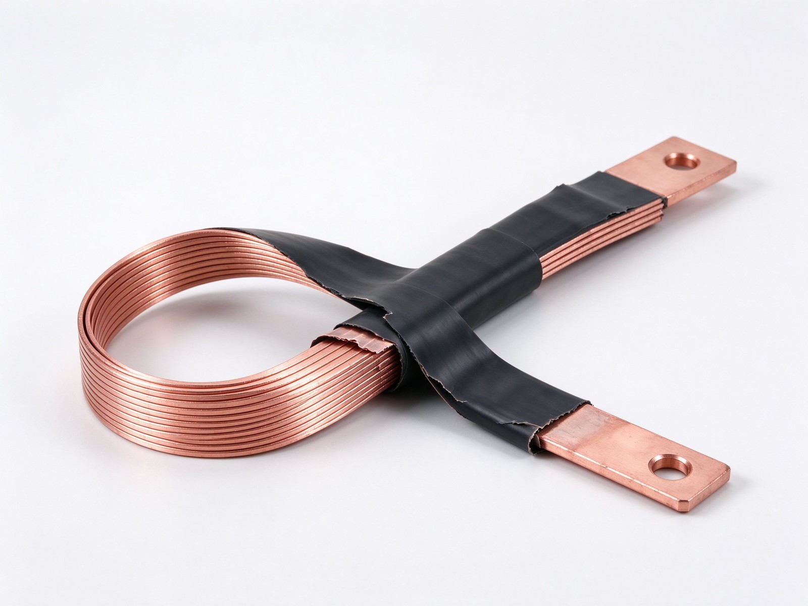
Aluminium busbar connectors sized by the copper-to-aluminium rule, plated and torqued for joint life - send a drawing for a quote.
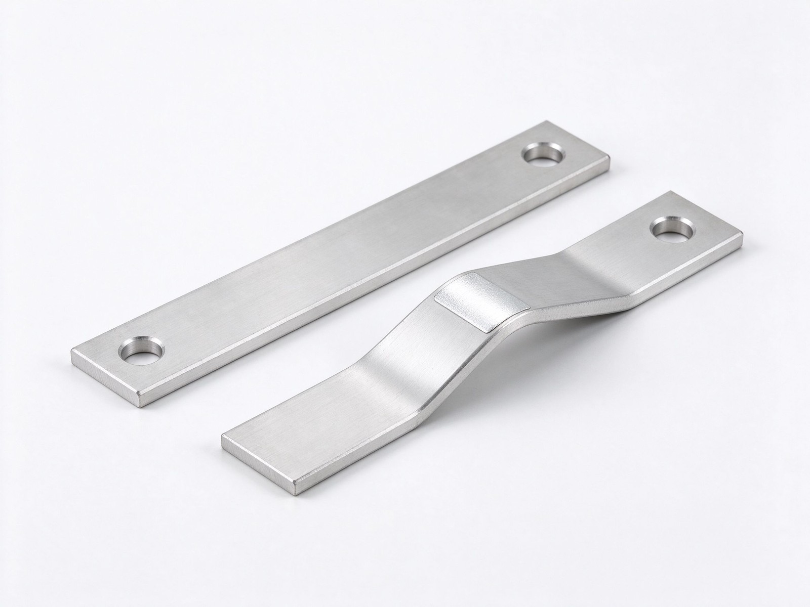
Product imagery: factory photo plus studio renders. The exact geometry, layers and terminals of your part follow your drawing.
Final values follow your drawing — this is the standard configuration of the family.
| Parameter | Value |
|---|---|
| Conductor | 6101-T6 aluminium, 57-61% IACS; 6061/6063 structural grades |
| Copper conversion | Width +27% or thickness +50% for equal temperature rise |
| Finish | Bare, tin plated, silver plated; epoxy powder coat option |
| Joints | Torque-controlled bolted connections per IEEE/UL/NEMA practice |
| Corrosion control | Tin or silver plating for H2S and humid environments |
| Formats | Straight bars, bent connectors, laminated or insulated aluminium sets |
| Fabrication | CNC punch, bend, drill, mill; plating in-house |
| SKU | SY-CM-315 |
Key characteristics of this product family.
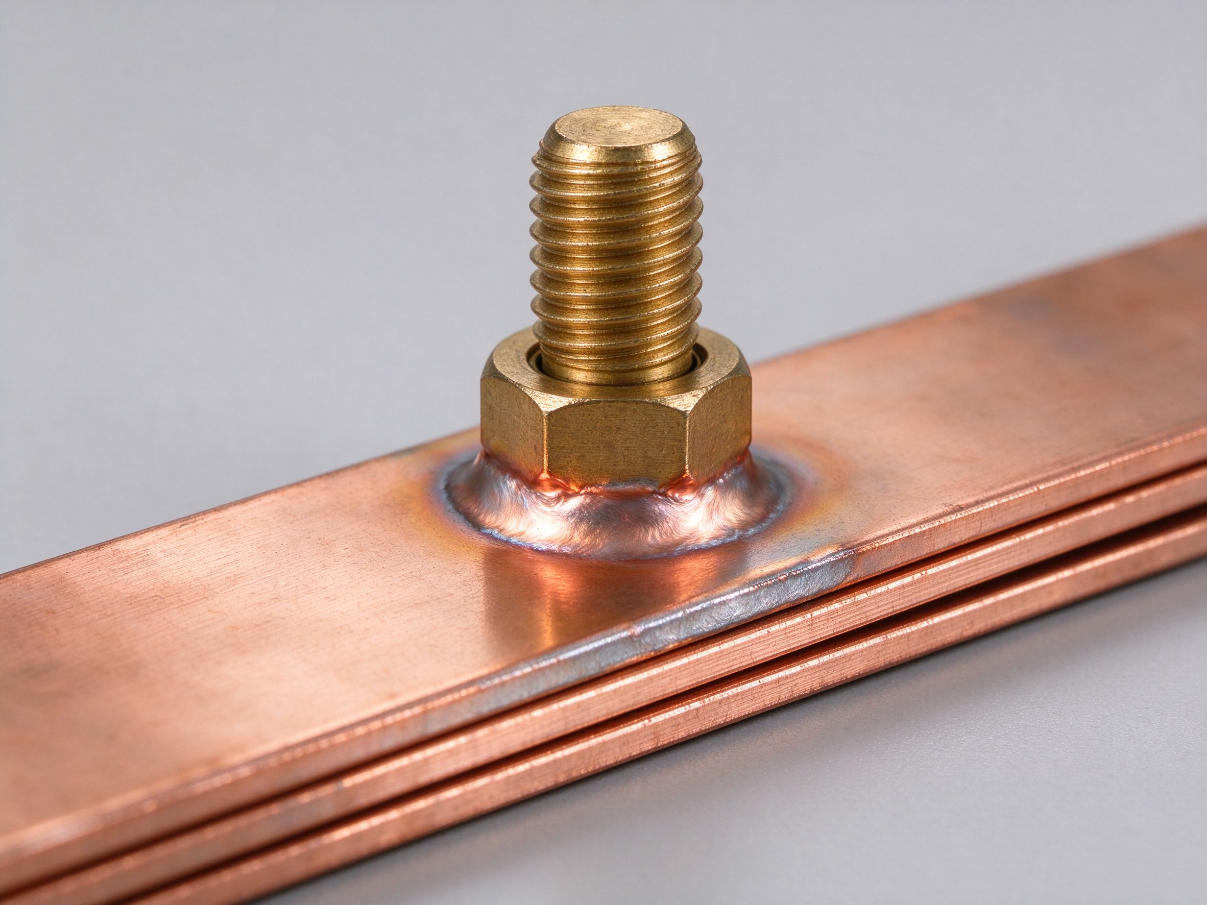
Aluminium busbar connectors are specified where heat can dissipate freely and metal cost is the deciding factor. The 6101 electrical grade delivers about 57 to 61 percent of copper's conductivity at roughly half the weight, so the bar ends up physically larger than its copper equivalent - which is exactly what you want in cabinets, breaker cubicles and control panels, where extra surface area helps cooling and the enclosure structure pays less for weight.
Sizing aluminium against copper follows a simple rule for the same temperature rise: make the aluminium section about 27 percent wider, or about 50 percent thicker. A 5-inch by quarter-inch aluminium bar matches a 4-inch by quarter-inch copper bar; a 4-inch by three-eighths aluminium bar matches a 4-inch by quarter-inch copper bar. Width beats thickness: doubling width from 4 to 8 inches raises ampacity by about 87 percent, while doubling thickness from a quarter to half an inch raises it only about 45 percent - even though both double the cross-section, because width also doubles the radiating surface.
Two physics effects then set the maintenance schedule. At high current the conductor surface runs cooler than its core - the outside radiates heat while the core must conduct it out - so internal resistance rises and voltage drop grows, which is why ampacity tables apply a thermal derating rather than a pure resistivity figure. Separately, aluminium expands and contracts about 42 percent more than copper, which slowly loosens bolted joints between runs and at equipment terminals: torque sequences, correct washer selection and a periodic re-torque interval are part of the design, not a service afterthought.
Environment sets the finish. Hydrogen-sulphide-rich atmospheres and extreme operating temperatures accelerate corrosion on both copper and aluminium joints, and silver or tin electroplating is the standard mitigation; where the bar sits in dirty or damp plant, an epoxy powder coat adds a dielectric skin on everything except the contact faces. Installation practice follows IEEE, UL and NEMA guidance for bolted connections, and SHANYUAN fabricates each connector from your drawing - plated, bent and drilled to the joint geometry your panel needs.
To hold the same temperature rise, size aluminium at roughly 27 percent wider than the copper bar it replaces, or about 50 percent thicker. Why prefer width: doubling width from 4 to 8 inches lifts ampacity near 87 percent, while doubling thickness from a quarter to half an inch lifts it only about 45 percent - both double the metal, but only width doubles the heat-radiating face. At high current a thermal skin effect adds derating: the surface radiates while the core runs hotter, so internal resistance and voltage drift up. Build from the ampacity chart and read the trade-offs in copper versus aluminium.
Aluminium grows and shrinks about 42 percent more than copper with temperature cycles, and that movement works bolted connections loose over time. Design for it: torque the joint in the manufacturer's sequence with the correct flat and lock washers, torque-check after commissioning, and set a re-torque interval in the maintenance plan. Where aluminium meets copper at equipment terminals, plated transition pieces stop galvanic buildup. Installation practice follows IEEE, UL and NEMA guidance - details in busbar connections and the aluminium busbar range.
Hydrogen-sulphide-rich atmospheres, coastal salt spray and extreme plant temperatures corrode both copper and aluminium contact faces; silver or tin electroplating is the standard mitigation, applied over the whole bar or restricted to the contact zones. Where the bar runs through damp, dusty or chemical plant, an epoxy powder coat adds a sealed dielectric skin while leaving contact faces bare. Send the joint drawing and environment notes through custom connector design and we will propose the finish.
Aluminium busbar connectors live or die at the contact face, where the conductor grade meets plating, bolt and thermal movement. The matrix below compares the three conductor materials that show up at these joints, column by column, so the transition design locks early.
| Joint-Design Property | 6101-T6 Aluminium | C11000 Copper | C10100 OFHC Copper | What It Means for the Connector |
|---|---|---|---|---|
| Electrical conductivity | 57-61% IACS | 100% IACS | 101% IACS | Why the 6101 aluminium distribution bar runs wider |
| Density | 2.70 g/cm3 | 8.89 g/cm3 | 8.94 g/cm3 | Aluminium joints load support brackets far less |
| Linear thermal expansion | 23 x 10-6 /K | 17 x 10-6 /K | 17 x 10-6 /K | More cycle movement to design the torque regime around |
| Surface oxide behaviour | Fast-growing, self-healing oxide | Slow tarnish | Slow tarnish | Plated transition pieces at every Al-to-Cu interface |
| Typical contact finish | Tin-plated contact zones | Bare or tin-plated | Bare or silver-flashed | Matched to the corrosiveness of the cabinet atmosphere |
| Galvanic pairing risk | High when paired bare with copper | Low within copper | Low within copper | Transition plates and washers stop fretting corrosion |
Every number above is a typical published value used for planning; the finished connector is approved against your equipment terminal drawing. Where the connector lands on a painted or anodized face, plan a scrape zone at the contact and specify the washer set in the drawing - painted interfaces are the second place aluminium joints fail after torque loss. Re-torque intervals live in the maintenance file rather than the joint note - the hardware is built to survive the interval between checks, not to remove the check. Engineers weighing the aluminium busbar sizing vs copper trade-off in full should read the dedicated copper versus aluminium comparison, and the plating and transition logic at mixed-material joints is detailed in busbar connection guidance.
Selecting aluminium busbar connectors on paper takes three passes, and the table below gives the first-pass numbers engineers ask for most. The flow assumes the bar itself is already sized to the feeder rating.
| 6101 Distribution Bar Size | Equipment Stud | Recommended Connector Form | Typical Installation Torque |
|---|---|---|---|
| 25 x 3 mm feeder | M6 | Straight plated lug | 9-10 Nm |
| 40 x 5 mm feeder | M8 | Offset transition plate | 22-25 Nm |
| 60 x 6 mm main | M10 | Double-bolt transition | 44-50 Nm |
| 80 x 6 mm riser | M12 | Inspection-friendly plate | 75-85 Nm |
| 100 x 8 mm feeder | M16 | Flexible-rated transition | 120-140 Nm |
Torque figures are typical values for plated steel hardware on clean, dry contact faces; the fastener manufacturer data sheet governs the final number. Because aluminium creeps under load, the maintenance plan needs a first re-check after commissioning and a periodic re-torque cycle - that aluminium connector torque maintenance logic is explained in the joint notes on busbar connection guidance, and size the underlying bar with the ampacity chart before ordering connectors. Check the creepage path across the connector body in dusty plants: a sealed transition plate keeps conductive dust bridges off the stud. On outdoor cubicles, add a boot or cover over the transition plate once the commissioning re-check is signed off, so re-entry stays a planned task rather than an emergency.
Where this busbar configuration earns its place.
Where this busbar configuration earns its place.
Where this busbar configuration earns its place.
Where this busbar configuration earns its place.
Where this busbar configuration earns its place.
Where this busbar configuration earns its place.
Your drawings reach the engineers who build the part.
Design risks flagged when changes are cheap.
Test records per lot, CoC and PPAP on request.
Drawing to delivered production parts, one supplier.
From spec review to shipped, tested parts — one accountable supplier.
Straight answers from the engineering team.
Every SHANYUAN busbar is custom, but the power circuits they connect recur across markets. Three typical ones — send us yours and we will point to the right stack-up.
Tight, low-inductance links between the battery source and traction inverters, fully edge-sealed for 400–800 V platforms.
Commutation-loop connections from DC-link capacitors to IGBT bridges, designed against switching overshoot V = L × di/dt.
Converter DC links built for rising bus voltages toward 1500 VDC, with creepage and partial-discharge margins included.
Construction, dielectric selection and current capacity basics.
Read the busbar design guideLayers, terminals, dielectrics and mounting are all configurable. Send us your spec for DFM review and a quotation within one business day.