Sizing a busbar is an 8-step procedure, not a single formula: determine the design current, apply a safety factor, compute the cross-section from material constants, round to a standard size, fix the width and thickness, check voltage drop under 3%, verify the temperature rise, and confirm the standard you are building to. This guide walks each step with numbers, then points you to the free calculator and the documented calculation we provide with every quotation.
Sizing a busbar is an 8-step procedure, not a single formula: determine the design current, apply a safety factor, compute the cross-section from material constants, round to a standard size, fix the width and thickness, check voltage drop under 3%, verify the temperature rise, and confirm the standard you are building to. This guide walks each step with numbers, then points you to the free calculator and the documented calculation we provide with every quotation.
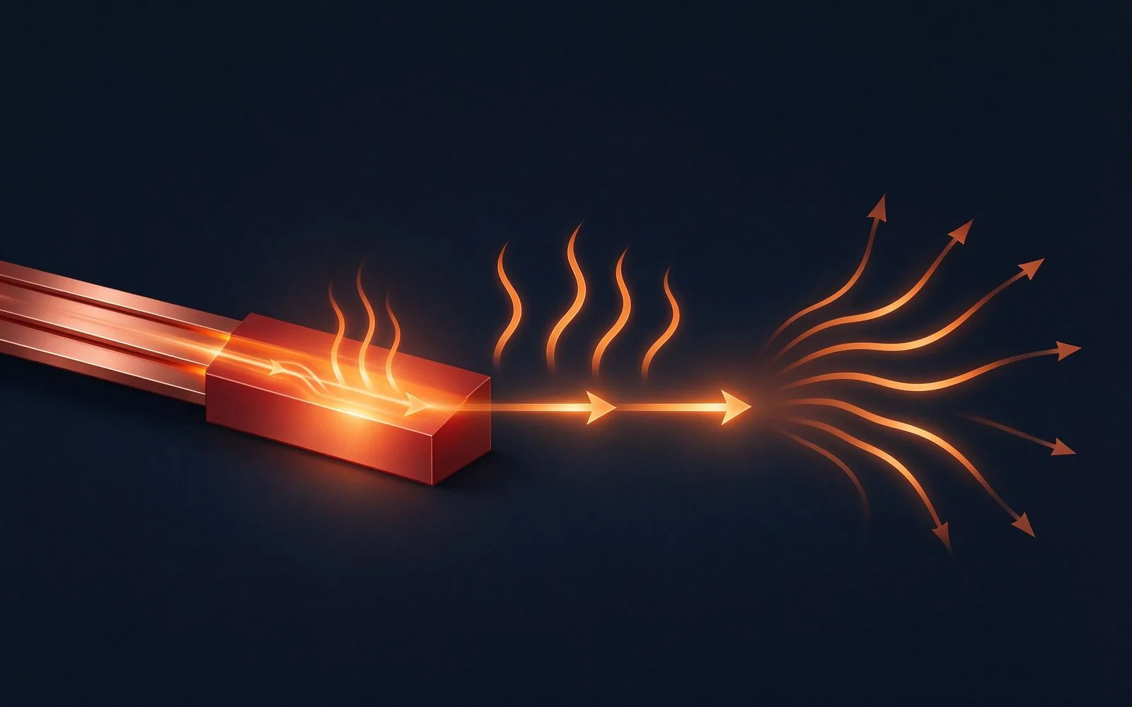
Every step feeds the next; skipping the thermal check is the most common cause of undersized bars. The full temperature-rise method — ΔT = (I/K)²/A with material constants — is documented in the ampacity calculation guide.
Start with the continuous load, not the peak: I_design = I_continuous × 1.25. The 1.25 factor absorbs three real effects: expected load growth, harmonic content that heats the bar beyond the fundamental, and the difference between a table rating and the installed condition. Adjust it upward (1.5–2.0) when the load is a motor group with inrush, when the enclosure is sealed, or when the busbar runs near heat sources.
For three-phase systems the input is usually power: I = P / (√3 · U · PF), with PF ≈ 0.95 unless the load is non-linear. If you already have a current number from the load study, use it directly and still apply the factor — the factor is not the load study; it is the margin on top of it.
The core sizing relationship is ΔT = (I/K)² / A: temperature rise ΔT in Kelvin is set by current I, a material-and-ventilation constant K, and cross-section A in mm². Rearranged, A = I² / (K² · ΔT). For copper in a ventilated enclosure K is roughly 8.5 at typical emissivity; for aluminum use roughly 5.5–6.0. The result is the minimum copper or aluminum section; the final bar must also satisfy the mechanical and short-circuit checks in later steps.
Cross-section alone never decides a rating — orientation, spacing, enclosure ventilation and ambient all shift the number by 20–40%. That is why the SHANYUAN busbar ampacity calculator takes mounting and ambient as inputs rather than returning a single table value.
Round the computed section up to the nearest standard: 10, 16, 25, 32, 40, 50, 63, 80, 100, 125, 160, 200, 250, 320, 400, 500, 630 mm². Then choose a width × thickness pair that (a) fits the assembly, (b) keeps the aspect ratio under roughly 10:1 so the bar is formable and terminates cleanly, and (c) accounts for skin effect at the operating frequency — at 50/60 Hz skin depth in copper is about 9–10 mm, so bars thicker than ~10–12 mm gain little from extra thickness; add width or parallel bars instead.
A common result: a 2000 A design at 40 K lands near 1,384 mm², met by a 160 × 10 mm copper bar with margin. For laminated stacks, the conductor layers are typically 0.3–2.0 mm foil stacked to the needed section, which keeps the skin effect negligible across the layer width; the multi-layer busbar page shows the layer-count options (1–6+) and the ampacity chart lists reference ratings by section, layers and rise.
Voltage drop across a busbar comes from resistance and, for long runs, inductance: V_drop% = (I · Z · L / U) × 100. Keep it under 3% at full load for distribution bars; for DC-link bars inside equipment the relevant number is the resistive drop plus the transient voltage overshoot from inductance, which is why laminates are chosen rather than long cable pairs. A rule of thumb: if the computed drop exceeds 3%, either enlarge the section or shorten the route — do not raise the limit to fit the bar.
The busbar vs cable comparison shows how the impedance per meter compares at 50 Hz and at switching frequencies, which is exactly where the 3% budget gets consumed differently by the two conductors.
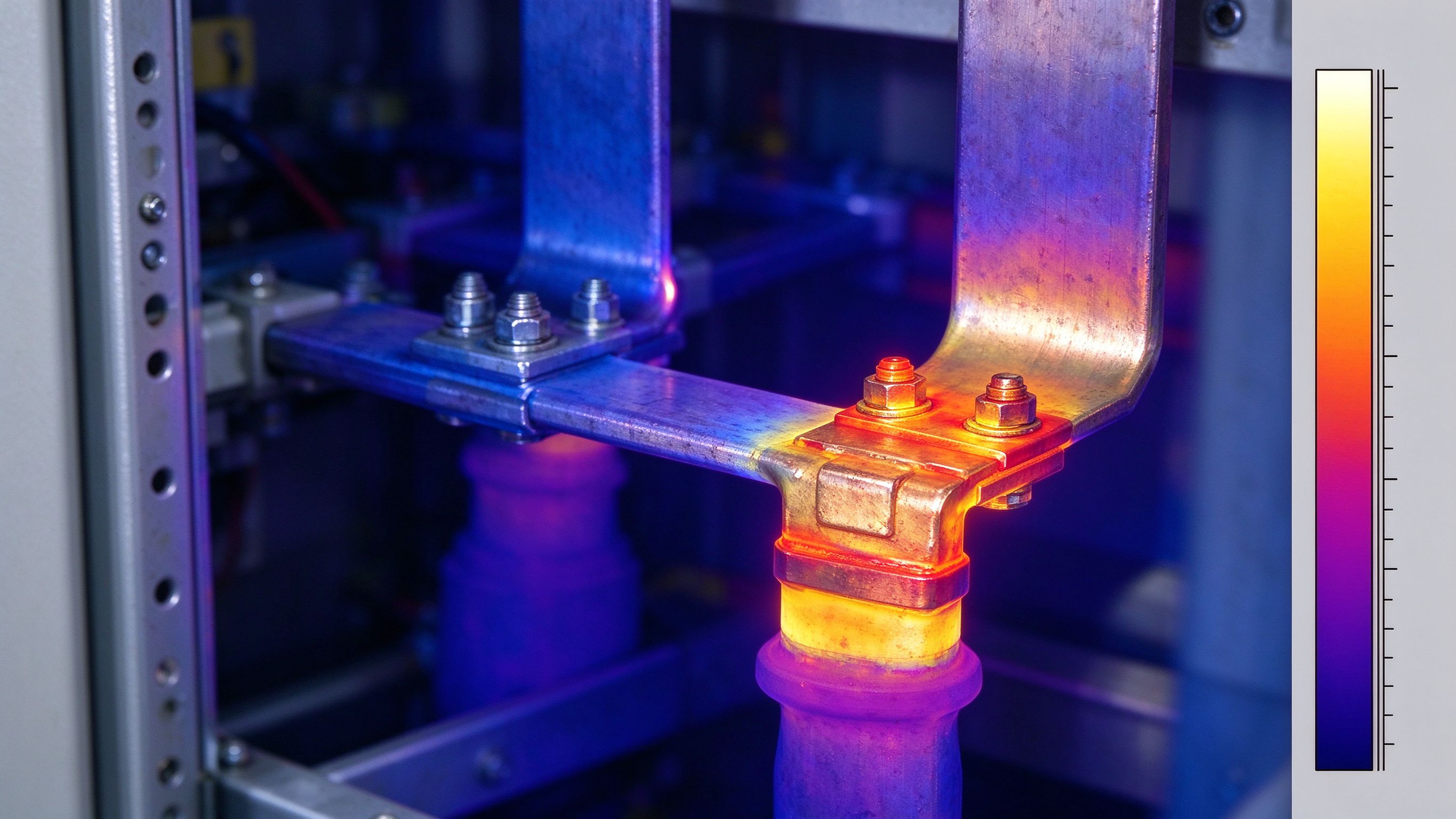
Verify the temperature rise at the actual conditions: ambient, enclosure sealing, ventilation, paint/plating emissivity, and grouping. Bare copper in free air at 30 °C rise is the reference; inside a sealed switchgear cubicle the same bar carries noticeably less. The acceptance limits are standard-defined — IEC 61439-1 permits 105 K / 90 K / 70 K for bare copper, bare aluminum internal connections and external terminals respectively; UL 891 is stricter for main busbars. If the bar fails the thermal check, re-enter the loop with a larger section or better cooling before going to manufacturing.
For a laminated stack the same rule applies with one advantage: the layers spread heat across a wide surface, so laminates typically run at 1.2–2.0 A/mm² under natural convection — about 1.5–2.5× the usable density of a bare bar of the same cross-section. The calculation guide works a full example with the derating curve.
Name the standard before you finalize the size — it changes the acceptance criteria. Three families matter for busbars:
If you export to India or the UK, specify the regional clause in the RFQ rather than assuming IEC compliance is accepted automatically. The supplier evaluation guide lists the documentation to request — test reports, material certs and the calculation itself — so the compliance claim is verifiable, not verbal.
Work a 400 A three-phase distribution bar at 40 °C ambient inside a ventilated enclosure:
Now verify the same number in the ampacity calculator with mounting and ambient set to your enclosure — then send the parameters to SHANYUAN engineering and the calculation comes back documented with the quotation.
The laminated busbar design guide covers the mechanical checks — supports, spacing and short-circuit forces — that follow once the section is fixed.
Use the free busbar ampacity calculator for a first estimate of copper or aluminum capacity by section, layers and mounting, the ampacity chart for reference tables, and the calculation guide for the method with worked numbers. When the size is close, the remaining decisions are dielectric class and terminals — see the dielectric selection guide and the design guide.
SHANYUAN documents the sizing calculation with every quotation: we take the current profile, voltage class, ambient and enclosure, size the bar, and return the calculation sheet with the drawing. Send the parameters or open a custom design request to start.
What safety factor should I use for busbar sizing? 1.25 as a minimum (100–200% adjustable in most calculators); use 1.5–2.0 for motor groups, sealed enclosures or harmonic-heavy loads.
What is the standard voltage-drop limit? Under 3% at full load for distribution bars; DC-link bars inside equipment are governed by resistive drop plus switching overshoot, where a laminate is usually specified.
Which standards apply to busbar sizing? IEC 61439-1 (assemblies), UL 891 / NEC (North America) and IS 60947 / BS EN 61439 for export projects to India and the UK. State the standard in the RFQ and request the documented calculation.
Is the SHANYUAN calculator a final design? No — it is a planning aid. The final size is reviewed against the actual enclosure, ambient, frequency and standards, and documented with the quotation.
A busbar's rating is not a lookup — it is a calculation. Temperature rise is the real limi
Read article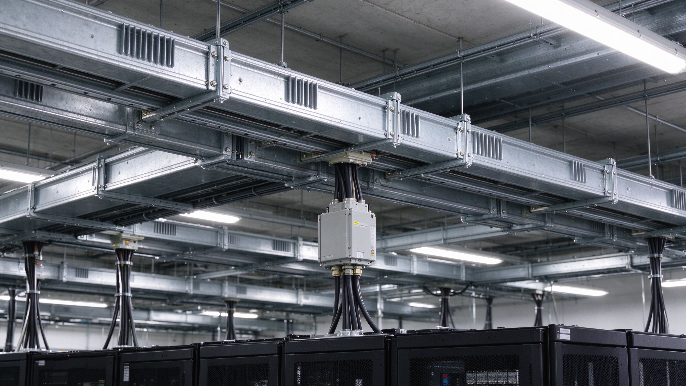
Busbars, bus ducts and cables all carry power — at different scales. This guide draws the
Read article
PET, Nomex and DLF epoxy are the three dielectrics we laminate into SHANYUAN busbars every
Read articleSend the current profile, voltage class and terminal types — our engineers reply within one business day.
