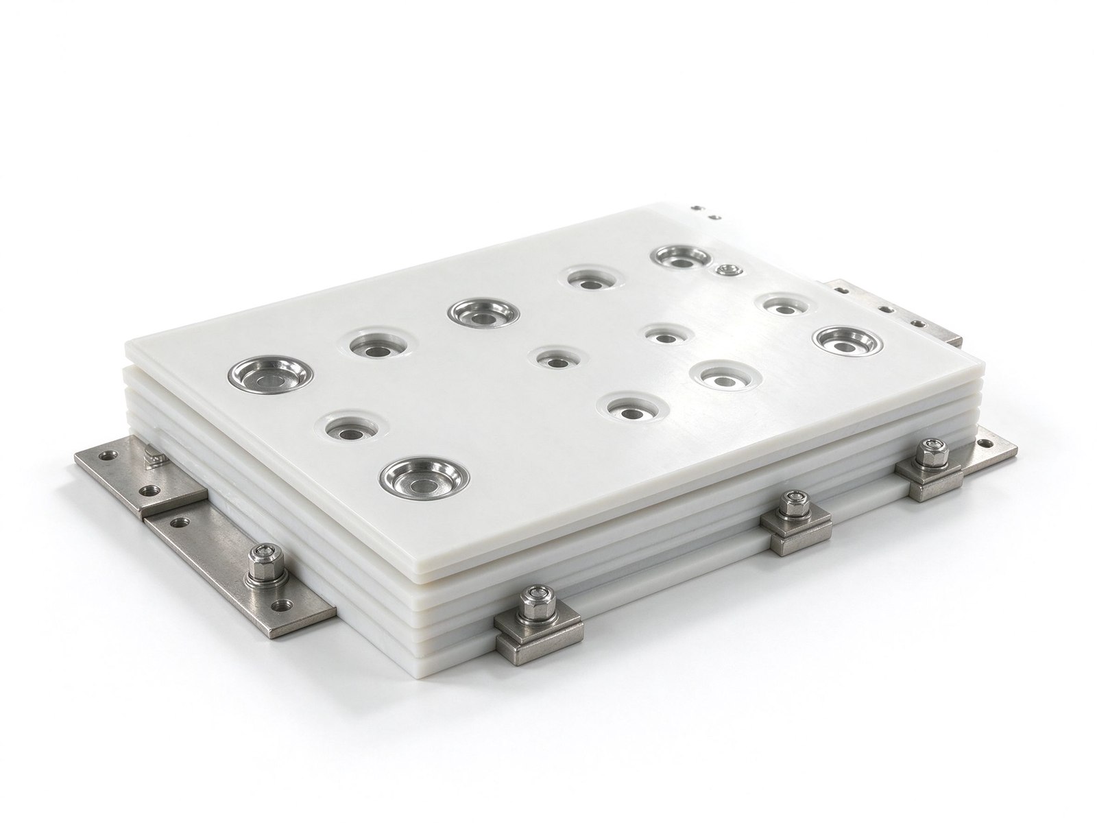
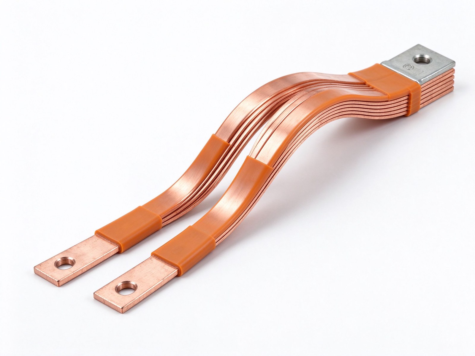
Copper busbar with continuous solid insulation to ground — compact clearances for tight enclosures.
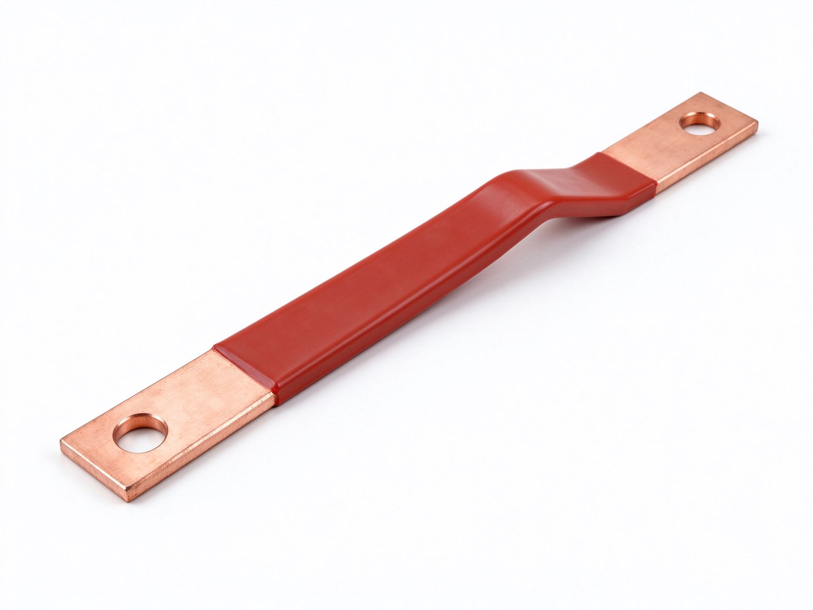
Product imagery: factory photo plus studio renders. The exact geometry, layers and terminals of your part follow your drawing.
Final values follow your drawing — this is the standard configuration of the family.
| Parameter | Value |
|---|---|
| Conductor | C11000 copper |
| Insulation | Solid dielectric layer to ground |
| Clearance benefit | Compact phase-to-ground spacing |
| Forms | Straight, bent, multi-branch assemblies |
| Terminals | Drilled lugs, studs or welded tabs |
| Environment | Indoor and harsh industrial |
| SKU | SY-CM-305 |
Key characteristics of this product family.
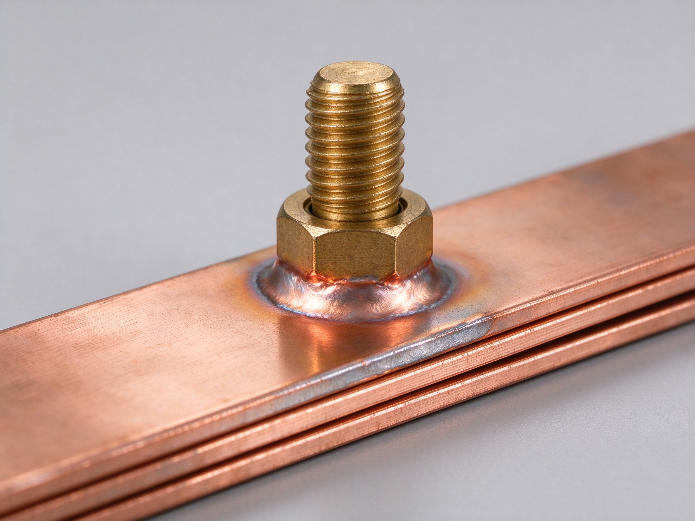
A solid insulated system (SIS) busbar carries a continuous solid insulation layer between each phase and the grounded structure, so live parts need far less air clearance and creepage distance than bare bar. This shrinks the power path inside enclosures, allows tighter bends and improves environmental protection — a practical choice from transformer connections to underground mining power distribution.
Where this busbar configuration earns its place.
Where this busbar configuration earns its place.
Where this busbar configuration earns its place.
Where this busbar configuration earns its place.
Where this busbar configuration earns its place.
Where this busbar configuration earns its place.
Your drawings reach the engineers who build the part.
Design risks flagged when changes are cheap.
Test records per lot, CoC and PPAP on request.
Drawing to delivered production parts, one supplier.
From spec review to shipped, tested parts — one accountable supplier.
Straight answers from the engineering team.
Every SHANYUAN busbar is custom, but the power circuits they connect recur across markets. Three typical ones — send us yours and we will point to the right stack-up.
Tight, low-inductance links between the battery source and traction inverters, fully edge-sealed for 400–800 V platforms.
ExploreCommutation-loop connections from DC-link capacitors to IGBT bridges, designed against switching overshoot V = L × di/dt.
ExploreConverter DC links built for rising bus voltages toward 1500 VDC, with creepage and partial-discharge margins included.
ExploreLayers, terminals, dielectrics and mounting are all configurable. Send us your spec for DFM review and a quotation within one business day.
Send drawings, current ratings and voltage class — DFM feedback and a quotation within one business day.