Flexible laminated copper shunt with pressure-welded solid ends that replaces rigid copper bar in tight spaces - request a sample.
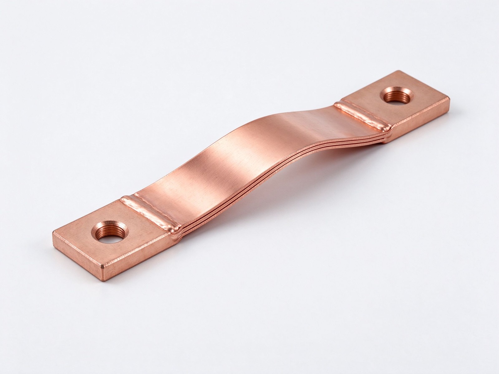
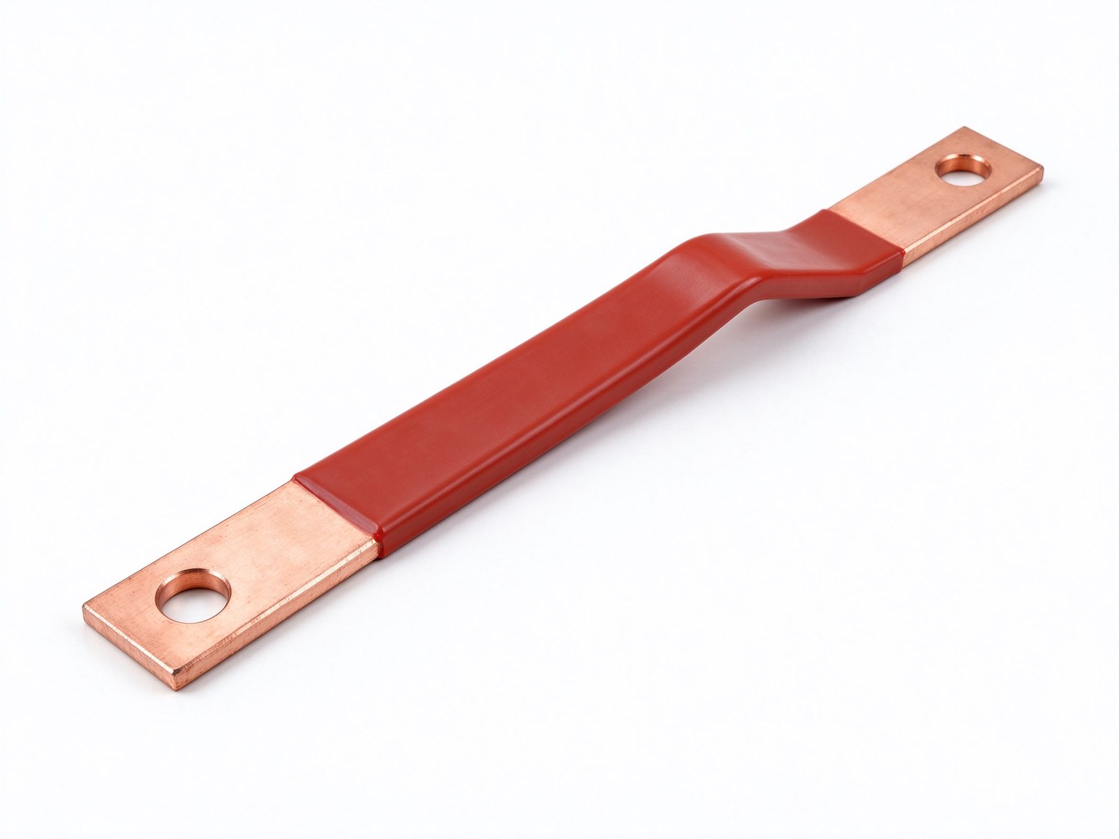
Product imagery: factory photo plus studio renders. The exact geometry, layers and terminals of your part follow your drawing.
Final values follow your drawing — this is the standard configuration of the family.
| Parameter | Value |
|---|---|
| Conductor | C11000 tinned copper laminates |
| Construction | Layered strip, pressure-welded / brazed ends |
| End blocks | Drilled, milled or tapped to drawing |
| Resistance | Matched to equivalent rigid copper bar |
| Current range | Full rigid-bar ampacity coverage |
| Life benefit | Up to ~1/3 longer vs soldered / bolted shunts |
| Mounting | Bolts in as a standard copper connector |
| SKU | SY-CM-321 |
Key characteristics of this product family.
A copper shunt of the power-duty type is a flexible laminated copper connector built to replace a rigid copper shunt bar in cramped or offset installations. It is worth being precise about terminology: a measurement shunt resistor is a precision milliohm device that drops a calibrated mV signal for metering. This power shunt is the opposite - a current-carrying link engineered to match the resistance of the solid copper bar it replaces, keeping current balanced and voltage drop in check across parallel paths.
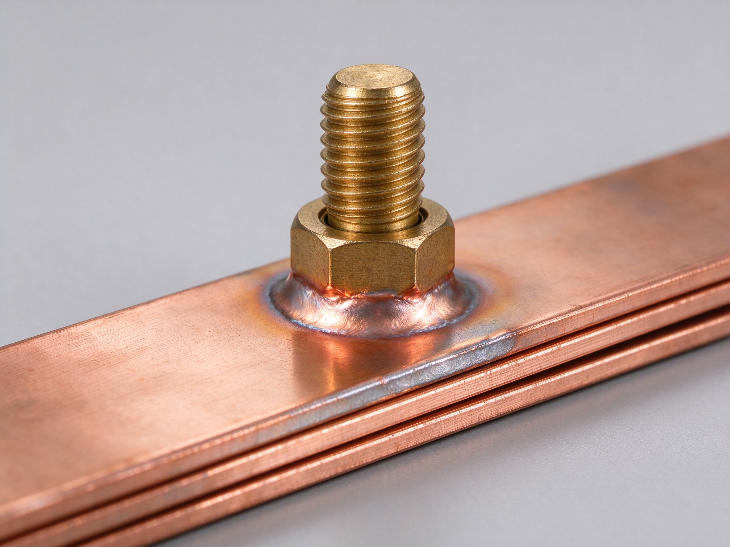
The flexible body stacks many thin copper laminates; both ends are pressure-welded or brazed into solid copper blocks. The middle stays flexible enough to absorb misalignment and vibration, while the ends behave like solid bar: drilled, milled or tapped to the exact hole pattern, then bolted in exactly like a standard copper connector. Because each layer fuses metallurgically into the terminal block, current distributes evenly across the whole bundle - no uneven current sharing, no hot spots at the joint.
Cross-section design follows rigid-bar ampacity logic: the total laminated area sets the continuous current rating, and the bonded end block sets joint temperature rise. We match the resistance and voltage drop of the original solid bar, so an exchange keeps the electrical behaviour of the system within design limits - a concern that matters most where parallel shunt runs share load.
Pressure-welded ends remove the two failure points flexible links usually die from: solder fatigue under thermal cycling, and loosening, oxidising bolted lap joints. Field service puts welded-shunt life about one-third beyond soldered or bolted builds. Typical duty covers power plants, substations, transformer leads, large motors, generators and switchgear cross-connections.
The word shunt names two unrelated parts. A measurement shunt resistor is a precision low-milli-ohm device that drops a calibrated mV signal - typically 60 mV at rated current - so a meter can read load current; it is chosen for accuracy class, burden and temperature coefficient. A power-duty copper shunt like this one is a busbar-class connector: resistance is held near solid-bar level, it outputs no calibrated mV signal, and it is selected on ampacity, voltage drop and joint temperature rise. Specify load current, required voltage drop and terminal layout - do not ask an accuracy class of it. Background on the layered-strip technology: flexible busbars.
Flexible copper links almost always fail at their ends. Solder creeps and fatigues through thermal cycles; bolted lap joints oxidise and loosen, adding contact resistance and local heating. When the laminate bundle is pressure-welded or brazed into a solid terminal block, the joint becomes bulk metal - the sheets and the terminal are one piece, current spreads evenly through every layer, and there is no interface left to degrade. That is why welded shunts run about one-third longer than soldered or bolted equivalents. The finished block then takes drilled holes for bolts, studs or braided-style flexibles - see our busbar connection guidance.
What current range do you cover? The layered bundle follows the rigid-bar ampacity table - from a few hundred amps to roughly 1,000 A and beyond. What end holes can you make? Welded ends are solid copper blocks: drill, mill, tap or slot to your drawing; M6 / M8 studs and blade terminals available. What plating? Tin is standard; nickel or silver on request for corrosion or low-contact-resistance joints. Send the rigid bar you want to replace - we engineer the equivalent flexible shunt in our custom design service, cross-checked against the ampacity chart.
The power-duty copper shunt on offer fuses two metallurgies into one part: the flexible laminate body plus the solid welded end blocks. The report below collects the typical material figures each build is quoted from.
| Stack Element | Typical Figure | Workshop Note |
|---|---|---|
| Flexible body | Stacked thin tinned copper laminates | Slides to absorb misalignment and vibration |
| End blocks | Solid C11000 copper, pressure-welded / brazed | Bulk metal at every drilled interface |
| Joint interface | Metallurgical fusion through all sheets | No solder creep, no bolted lap in the body |
| Standard finish | Tin plating on the blocks | Welded copper shunt connectors for indoor duty |
| Optional finishes | Nickel plating or silver plating, quoted on request | Corrosive plants or low-resistance joints |
| Conductive area | Matched to the replaced solid bar | Voltage drop held near the original path |
| Flexion travel | few mm excursion, planned on drawing | Dictates the bundle free length |
| Insulating parts | None in the standard build | RoHS / REACH baseline still applies |
| Documentation | Mill certificates, CoC on request | Ask when ordering |
Because the standard shunt carries no insulator, the compliance statement stays at the RoHS / REACH baseline level: there is no flammability claim to make on a bare part, and no certification claim is implied here. The pressure-welded end is what lets the welded shunt outlive soldered flexibles, and the flexible-family design rules are detailed in flexible busbar engineering notes. The bundle is specified by total conductive area rather than by sheet count - layer number is our internal choice once the area, bend radius and flex travel are fixed. Send a quick sketch first: bundle area, end-block drill pattern and expected motion usually settle the concept in one reply.
An OEM copper shunt is engineered backwards from the rigid bar it replaces, and three steps get the first-drawing answer most OEMs need.
| Input Stage | What You Send | DFM Pass Outcome |
|---|---|---|
| Bar equivalence | Solid bar section and rating | Laminate bundle sized to the same voltage drop |
| Movement budget | Offset, vibration, expansion | Free-flexing middle length and bend plane |
| Terminal interface | Studs, holes, torque class | Machinable solid end block drawing |
| Environment | Plant atmosphere notes | Tin, nickel or silver finish decision |
| Forecast volume | Annual or project quantity | Pricing and lot traceability plan |
| Package and label | Volume, packaging notes | Lot-coded packs for assembly lines |
Because each layer fuses into the end block, current spreads evenly across the bundle, and the resistance match keeps parallel paths balanced. The rating pass itself opens on the ampacity chart, and the joint side of the design follows busbar connection practice. Because the middle flexes while the ends stay solid, the bundle also damps small vibrations travelling between the two machines - a side benefit engineers value on genset and transformer trains. Because the ends mirror the original bar's hole pattern, the exchange keeps bolt count, washer set and torque procedure unchanged from the rigid installation - site work needs no new method statement. Tin is the default block finish for indoor plants; move to nickel where washdowns are daily, and to silver where the joint must stay low-resistance for decades of cycling. Send the bar drawing and the OEM program notes through contact for the first-pass quote.
Where this busbar configuration earns its place.
Where this busbar configuration earns its place.
Where this busbar configuration earns its place.
Where this busbar configuration earns its place.
Where this busbar configuration earns its place.
Where this busbar configuration earns its place.
Your drawings reach the engineers who build the part.
Design risks flagged when changes are cheap.
Test records per lot, CoC and PPAP on request.
Drawing to delivered production parts, one supplier.
From spec review to shipped, tested parts — one accountable supplier.
Straight answers from the engineering team.
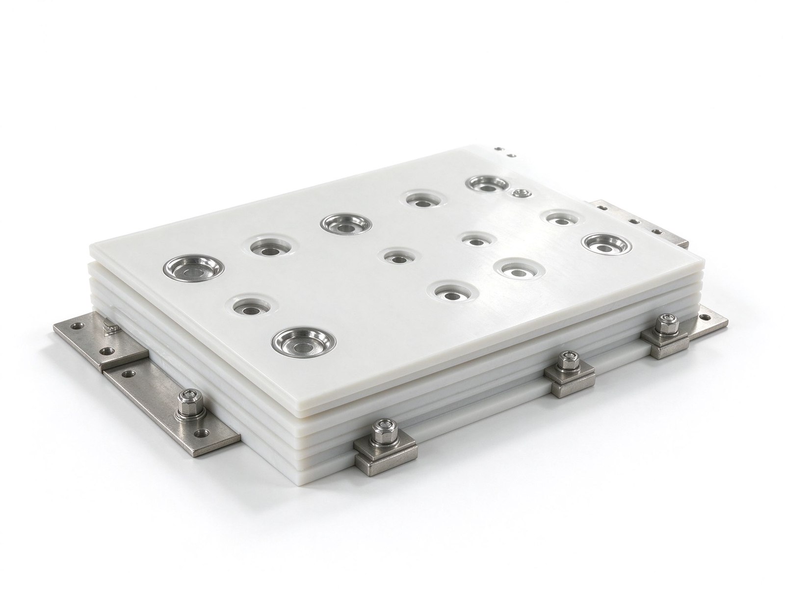
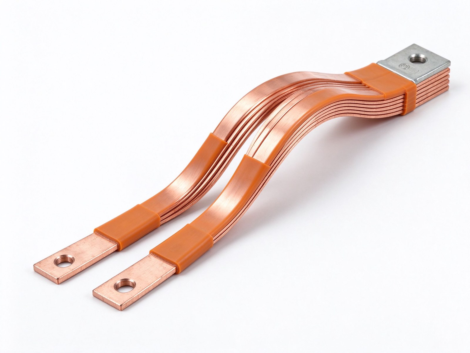
Every SHANYUAN busbar is custom, but the power circuits they connect recur across markets. Three typical ones — send us yours and we will point to the right stack-up.
Tight, low-inductance links between the battery source and traction inverters, fully edge-sealed for 400–800 V platforms.
Commutation-loop connections from DC-link capacitors to IGBT bridges, designed against switching overshoot V = L × di/dt.
Converter DC links built for rising bus voltages toward 1500 VDC, with creepage and partial-discharge margins included.
Construction, dielectric selection and current capacity basics.
Read the busbar design guideLayers, terminals, dielectrics and mounting are all configurable. Send us your spec for DFM review and a quotation within one business day.
