Insulated copper busbar with a solid dielectric to earth (SIS): smaller footprint, fewer arc-flash events, protection in oil, moisture and corrosive plants - get a quote.
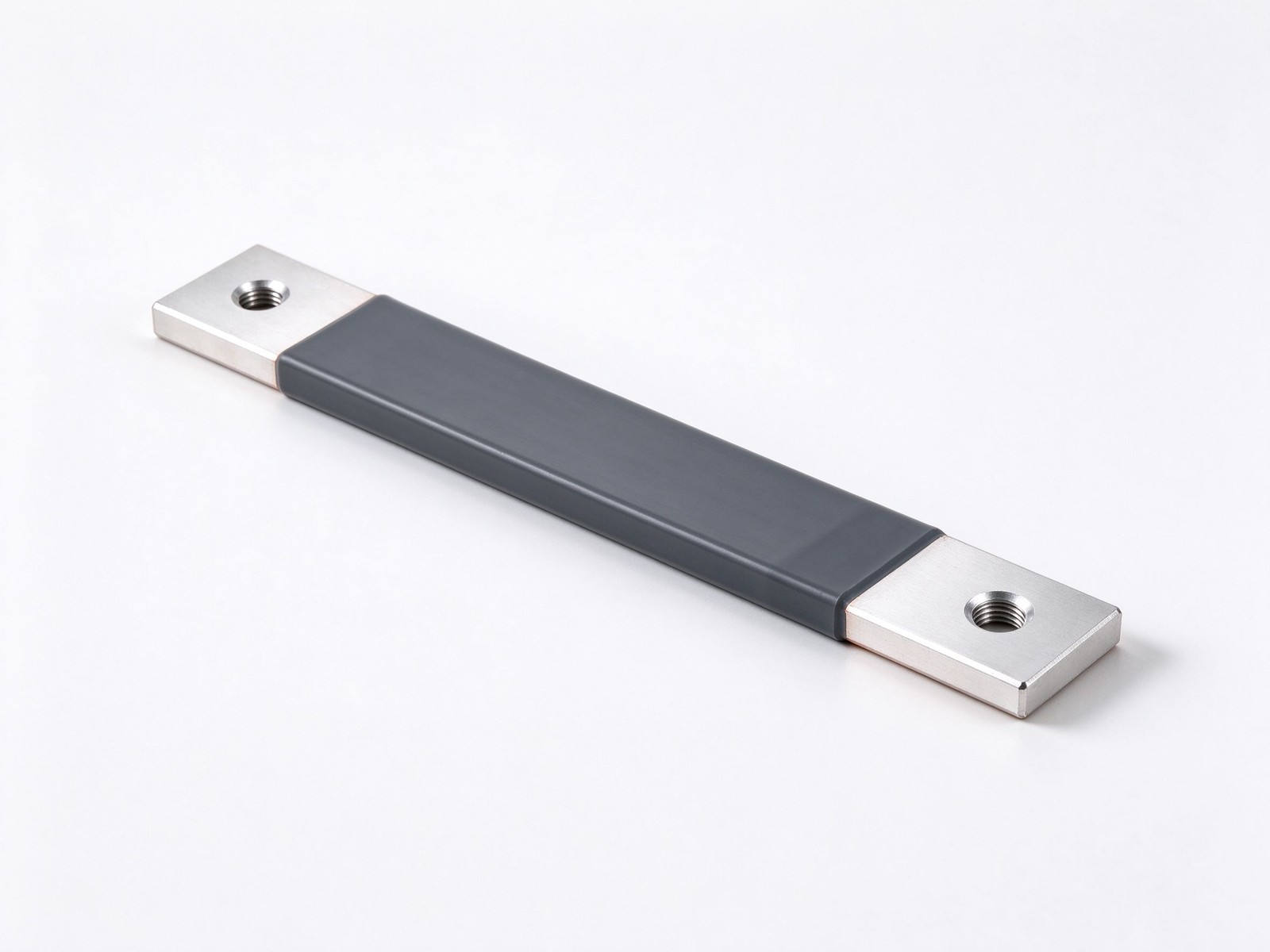
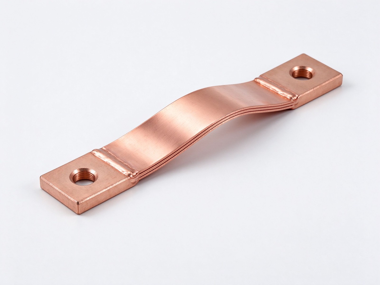
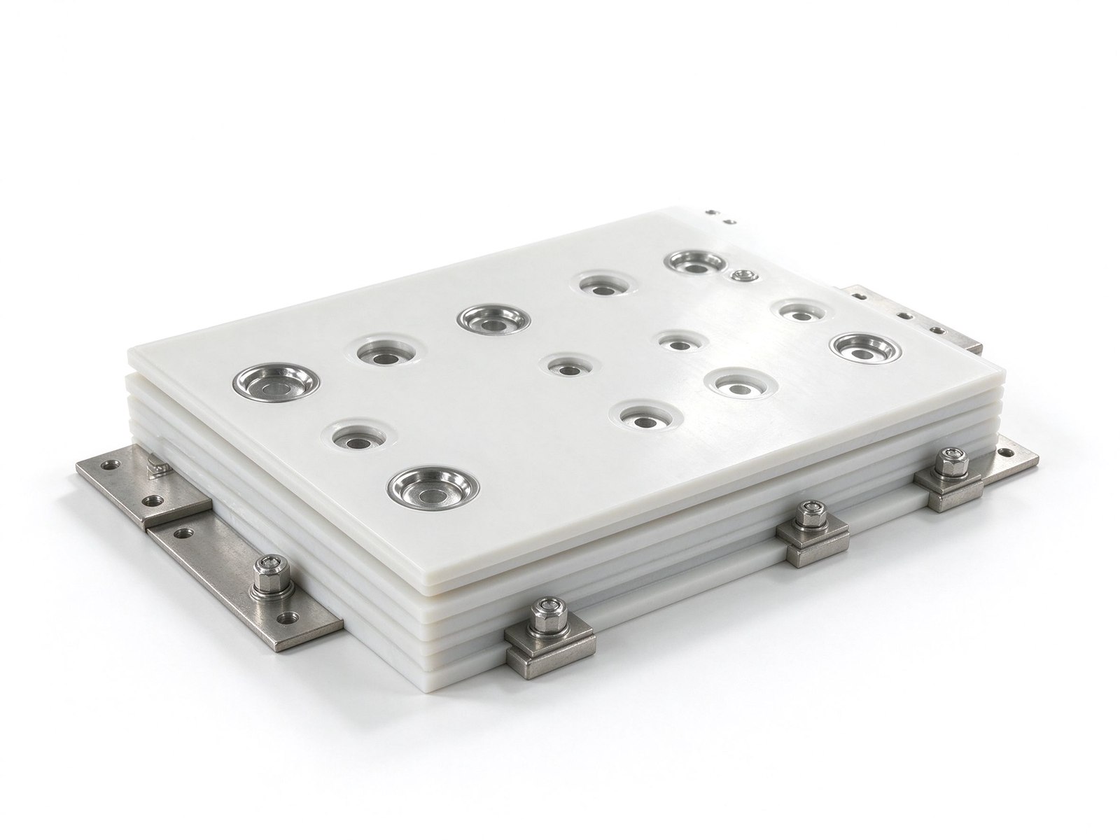
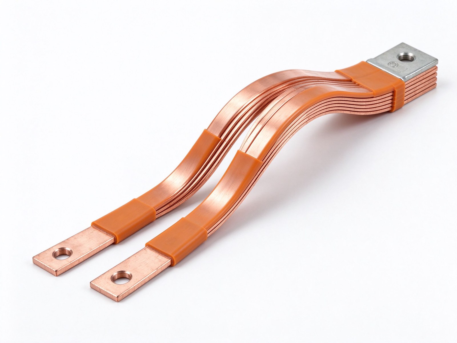
Product imagery: factory photo plus studio renders. The exact geometry, layers and terminals of your part follow your drawing.
Final values follow your drawing — this is the standard configuration of the family.
| Parameter | Value |
|---|---|
| Conductor | C11000 solid copper; aluminium section on request |
| System type | Solid insulation to earth (SIS), phase-potential bar |
| Outer surface | Grounded dielectric, no exposed live copper |
| Bend radius | Tighter than open-phase bar; no creepage gaps required |
| Environments served | Oil, sawdust, moisture, caustic and corrosive atmospheres |
| Stock depth | 450+ standard and metric copper sizes and shapes |
| SKU | SY-CM-320 |
Key characteristics of this product family.
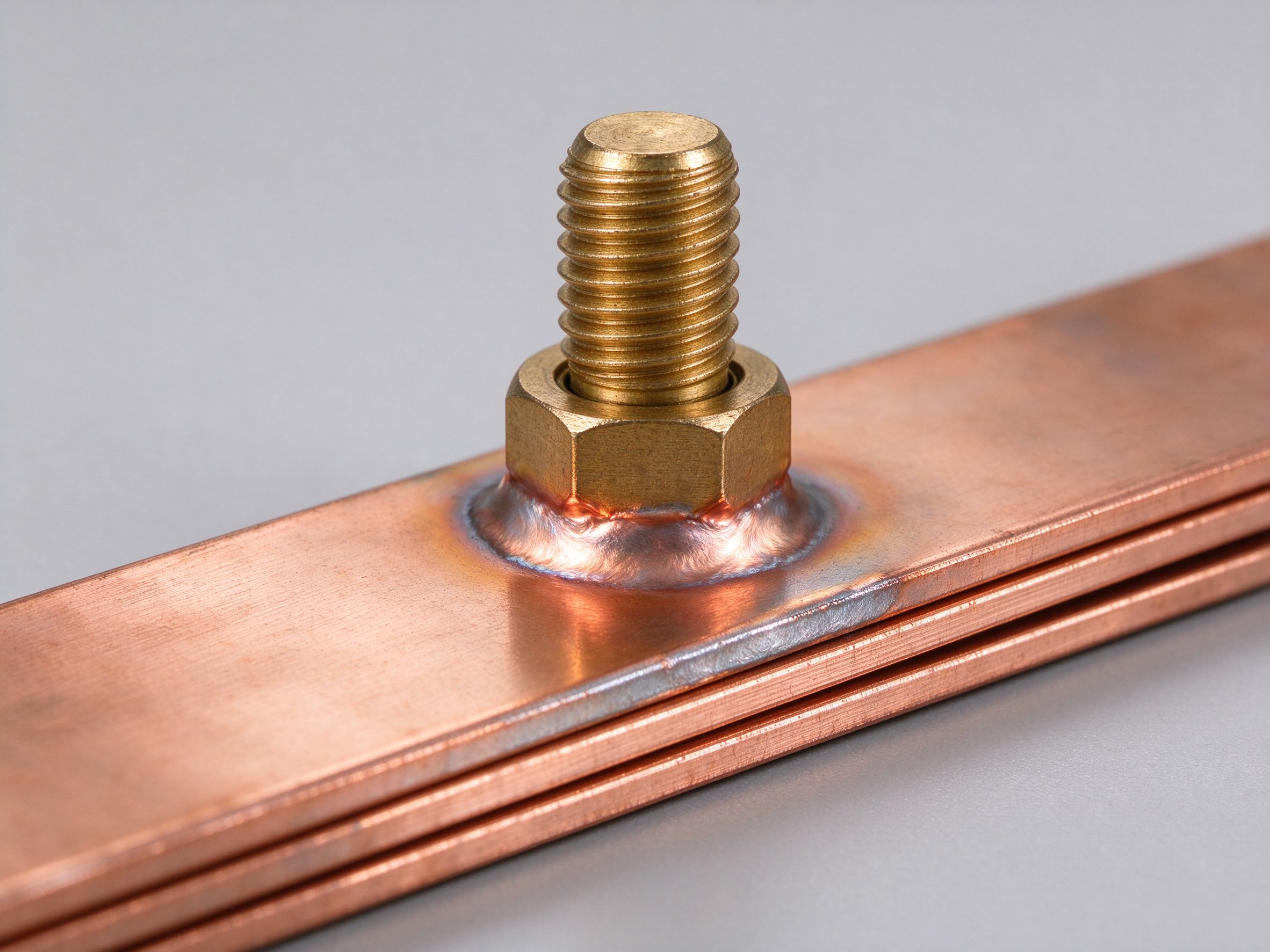
An insulated copper busbar - also built as a solid insulated system (SIS) - wraps a continuous dielectric around each phase conductor so the bar operates at full phase potential while everything outside the insulation sits at earth. It is the standard way to improve grounding inside switchgear, switchboards and busway or bus-duct runs, and it scales from transformer-bushing connections down to underground mining distribution.
Five engineering benefits drive the choice. The circuit footprint shrinks: tight bend radii replace wide open-phase clearances, and creepage and leakage-distance problems disappear, so more watts fit in less space. Safety improves because personnel face a grounded outer surface rather than exposed phase copper. Reliability rises because arc-flash and short-circuit events - such as wildlife bridging adjacent phases - are far less likely. The conductor gains protection in hostile plants with oil, sawdust, moisture or caustic materials, and its impedance stays low because surface corrosion and surface defects are suppressed at the dielectric interface.
We stock more than 450 standard and metric copper sizes and shapes for SIS builds, alongside thousands of ceramic and standoff insulators, so short runs and replacements ship fast.
Open-phase copper relies on air clearance and creepage distance between bars, which is why switchgear cubicles are so wide. A solid insulated conductor puts the dielectric where the stress actually is - directly on the copper - and lets the bars sit close, bend tightly and survive foreign objects bridging phases. The paybacks are concrete: lower personnel-injury risk, fewer arc-flash and short-circuit events, a conductor protected against oil, sawdust, moisture and corrosion, and reduced impedance as surface defects stay below the insulation. See how the idea scales on the dedicated solid insulated copper busbar page, and compare finishes with heat-shrink insulated busbars.
Not every insulated bar needs a full SIS jacket. Choose between three routes: epoxy powder coating for irregular one-off shapes applied after all bending and machining (see dielectric epoxy coating); laminated grounding bars where stacked insulated conductors replace open-phase runs (see multi-layer laminated busbars); and flexible insulated bars where vibration or thermal movement must be absorbed (see flexible insulated busbars). Our engineers will match the finish to your voltage class and ambient.
SIS builds lean from 450+ stocked copper sizes and shapes, cut to your drawing, with the insulation applied after fabrication. Mounting hardware comes from the same shelf: browse standoff insulators for support blocks and grounding busbar kits for the earthing side of the cubicle. Send the one-line diagram and the cubicle layout through contact - engineering answers within one business day.
An insulated copper busbar is judged on the dielectric as much as on the copper: the insulation carries the phase voltage to earth while the outer surface stays touch-safe. The table below lists the typical material figures an SIS build is quoted from.
| Dielectric Item | Typical Figure | Design Note |
|---|---|---|
| Conductor | C11000 solid copper, aluminium section on request | Same conductor family as our stock bars |
| System type | Continuous solid insulation to earth (SIS) | The solid insulated busbar SIS construction |
| Outer surface | Grounded dielectric, no exposed live copper | Arc flash risk drops at the touch point |
| Insulation finishes available | Epoxy powder, heat-shrink, film wrap | Picked by shape, voltage and environment |
| Insulator flammability | UL 94 V-0 on insulation parts, material level | Material-level statement |
| Hi-pot check | 100% before shipment | Confirms the arc flash busbar insulation integrity |
| Bend radius | 2-3 x bar thickness, planning value | Set by dielectric thickness, confirmed on drawing |
| Operating temperature band | -40 to +105 C planning range | Tightened by the chosen dielectric |
| Compliance baseline | RoHS / REACH baseline on every shipment | Standing lot-level statement |
These are typical material values, not a type-tested certificate list: the unit-level hi-pot check is what proves each bar, and batch documentation follows on request. The payback logic - compact footprints, fewer phase bridges, oil and moisture protection - is expanded in the design guide for insulated systems, and the current sizing pass begins with the ampacity chart. Where the run passes through oil or sawdust in a mill, the sealed dielectric also keeps the conductor surface clean - the tracking corrosion that normally grows under open-phase bars never reaches the copper surface itself.
Selecting an insulated copper busbar for switchgear follows three questions, and the table pairs each question with the input your one-line diagram already contains.
| Design Question | Typical Input From Your Drawing | How We Size the SIS Build |
|---|---|---|
| Voltage and phases | Up to 1,000 V class, 3-phase | Dielectric thickness and bend radius |
| Envelope | Cubicle width, busway run length | Phase pitch and bend layout |
| Ambient stress | Oil, moisture, conductive dust | Epoxy, shrink or film finish choice |
| Fault duty | Short-time rating | Conductor section and support spacing |
| Replacement parts | Existing bar size from stock list | Cut-from-stock, insulated on demand |
| Insulation repair field | Local touch-up or whole-bar resleeve | Planned by finish type |
The advantage of the solid-insulation route is that creepage and clearance debates shrink: the dielectric sits on the copper, so the insulated copper busbar switchgear build packs more amps into the same cubicle. Replacement parts draw on a 450+ size copper stock shelf, so a failed cubicle bar does not wait on a long extrude lead time. For retrofit cubicles where the old open-phase spacing must be reused, the insulated bar often drops in without modifying the bus chamber, because the touch-safe outer surface carries the safety duty that air gaps used to. The touch-safe outer surface also shortens permit-to-work wait times on live-panel inspections. For the current pass that starts the section choice, work the ampacity chart first, and walk the finish trade-offs in the SIS design guide.
Where this busbar configuration earns its place.
Where this busbar configuration earns its place.
Where this busbar configuration earns its place.
Where this busbar configuration earns its place.
Where this busbar configuration earns its place.
Where this busbar configuration earns its place.
Your drawings reach the engineers who build the part.
Design risks flagged when changes are cheap.
Test records per lot, CoC and PPAP on request.
Drawing to delivered production parts, one supplier.
From spec review to shipped, tested parts — one accountable supplier.
Straight answers from the engineering team.
Every SHANYUAN busbar is custom, but the power circuits they connect recur across markets. Three typical ones — send us yours and we will point to the right stack-up.
Tight, low-inductance links between the battery source and traction inverters, fully edge-sealed for 400–800 V platforms.
Commutation-loop connections from DC-link capacitors to IGBT bridges, designed against switching overshoot V = L × di/dt.
Converter DC links built for rising bus voltages toward 1500 VDC, with creepage and partial-discharge margins included.
Construction, dielectric selection and current capacity basics.
Read the busbar design guideLayers, terminals, dielectrics and mounting are all configurable. Send us your spec for DFM review and a quotation within one business day.