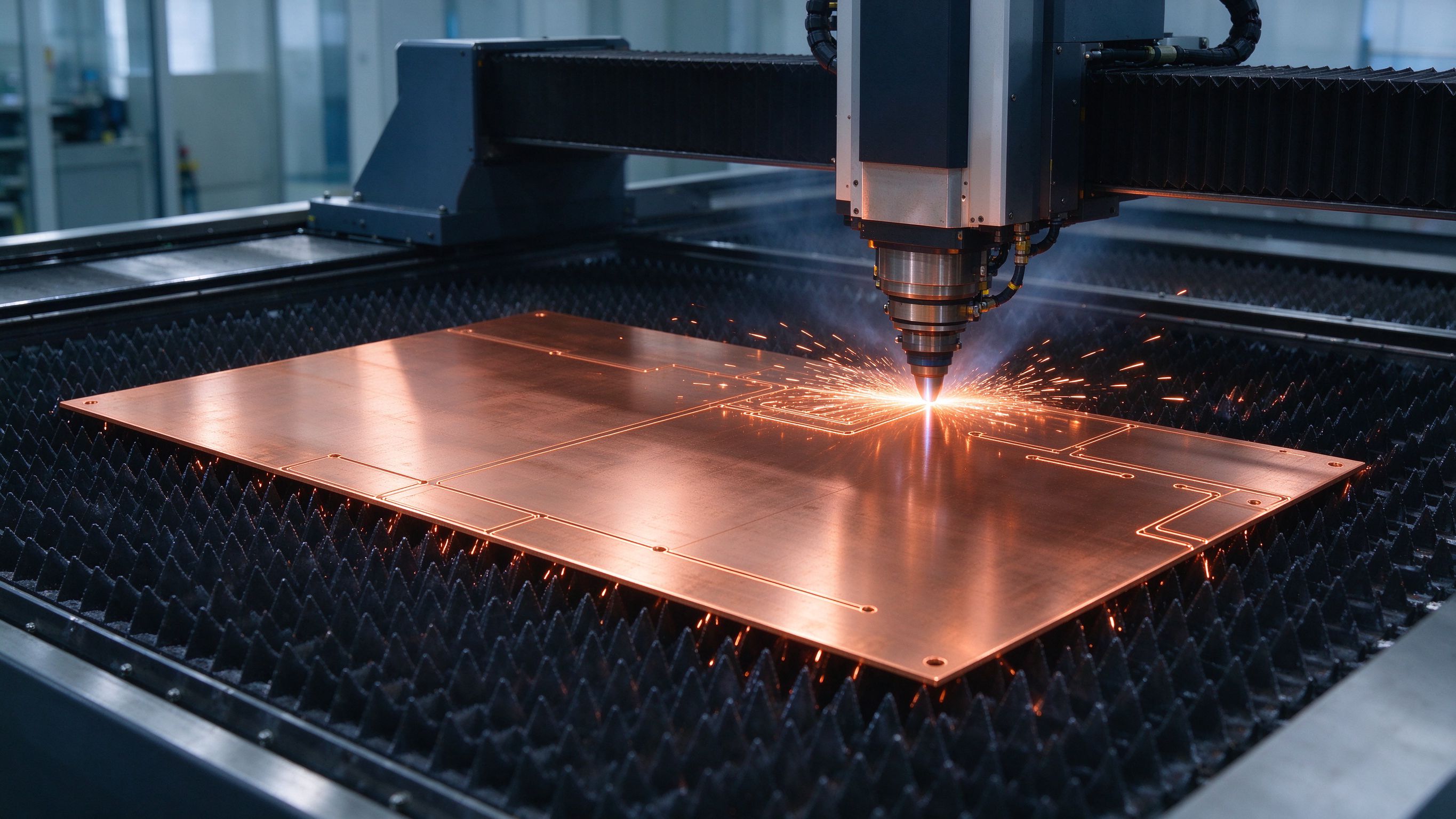
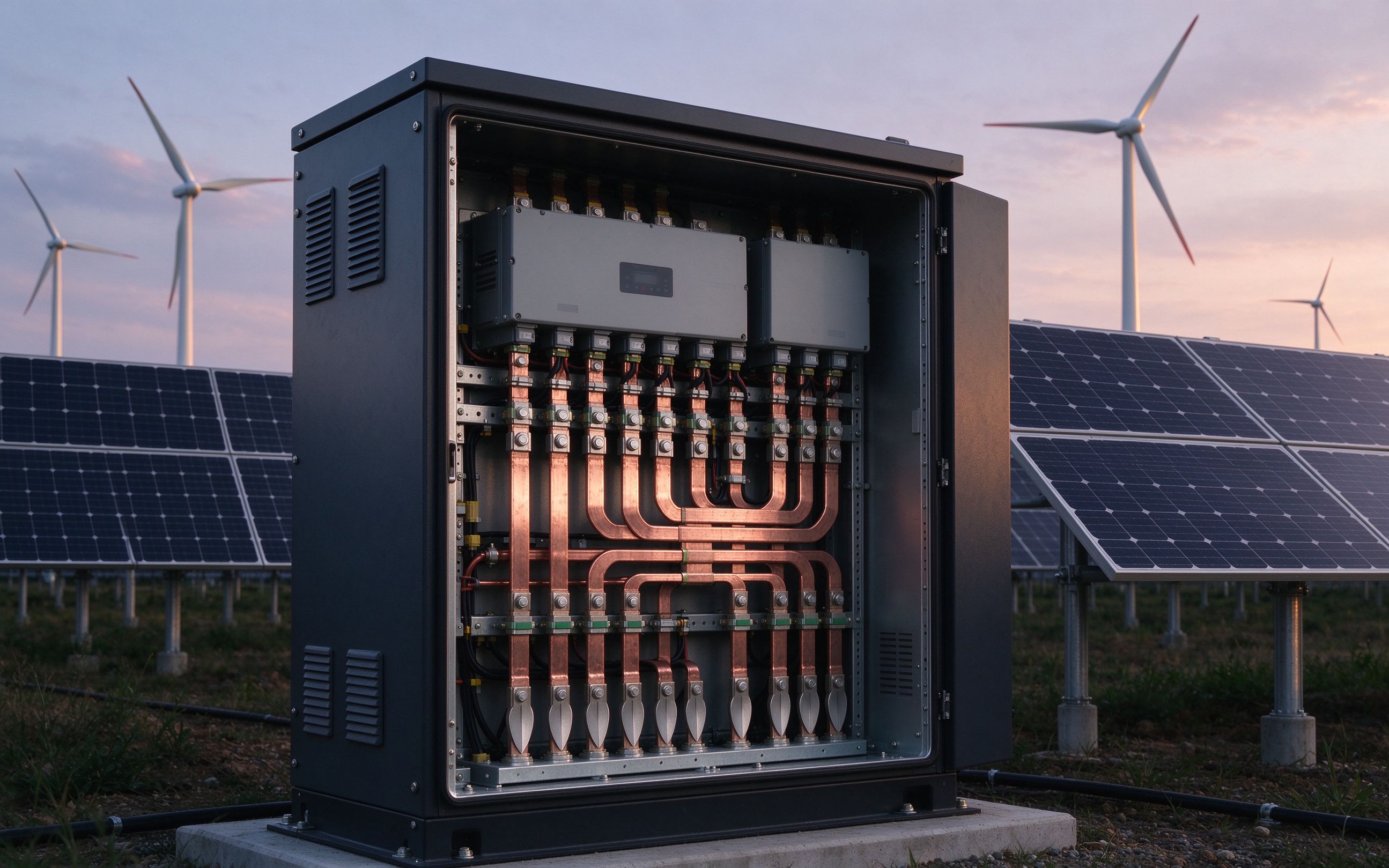
PV inverters and wind converters convert variable DC into grid-grade AC — and next-generation designs switch faster and run up to 1600 VDC. Our solar inverter busbars keep the DC link low-inductance, insulated and PD-controlled.
The four places busbars carry current in this application.
Formangepasste Laminate, die Gleichstrom aus den String-Sammelboxen zum DC-Eingang des Wechselrichters führen.
Die niederinduktive Wirbelsäule zwischen der DC-Link-Kondensatorbank und der IGBT/MOSFET-Brücke.
Hochstrom-Verbindungen zwischen generatorseitigem Gleichrichter und netzseitigem Umrichter in der Gondel.
Gepulste Schienen für Crowbar-Schaltungen und Dump-Widerstände bei Netzfehlern.
Kompakte niederinduktive Pfade für Vorladewiderstände und Entladeschaltungen im Schaltschrank.
Hybrid-Leistungs-/Signal-Layouts, die Treibersignale neben der Leistungsebene führen für kompakte Wechselrichterstufen.
1000 V oder 1500 V (1600 VDC-Referenz) — Dielektrikum, Kriechstrecke und Luftstrecke werden dadurch festgelegt.
Wohn-, Gewerbe- oder Netzniveau sowie Dauer- gegenüber Taktbetrieb — das prägt die Derating-Wahl.
Outdoor, containerisiert oder Offshore: Feuchteklasse, Salzbelastung und Umgebungsbereich bei Angebotserstellung.
Kondensatorpositionen und IGBT-Modul-Datenblatt-Teilung definieren die niederinduktivste Kommutierungsschleife.
Natürliche Konvektion oder Umluft — die Leiterdimensionierung folgt dem thermischen Design.
In wind turbines and solar farms, power semiconductors convert variable-voltage inputs into fixed-voltage outputs for grid connection. A solar inverter converts the variable DC of a PV array into utility-frequency AC — it is the key, often most expensive, component of the system, and it is growing more complex as semiconductors deliver faster switching and higher power density. Power ranges from a few kilowatts in residential units into the megawatt range at utility scale.
The laminated busbar is the connection between the DC source, the DC-link capacitors, resistors, drive circuitry and the IGBT/MOSFET modules — the low-inductance spine of each inverter stage. Next-generation converters use multilevel switching topologies with faster switches and operating voltages up to 1600 VDC, demanding improvements throughout the conversion chain. That voltage climb raises the bar on isolation, creepage/clearance and partial discharge: trapped air bubbles at insulation interfaces are a root cause of PD, and continuous discharge above the industry reference level of 10 pC degrades insulation over time. We cover the physics in our notes on low-inductance busbar design.
Environment is the other half of the design. PV inverters run essentially continuously, so high humidity robustness and low lifetime cost matter more than power-cycling tolerance; wind converters in nacelles face varying temperatures, humidity and salt exposure offshore. Where cooling margins shrink — concentrated PV dense arrays especially — designs lean on high-temperature dielectric systems rated up to 130 °C continuous versus 105 °C standard, pushing more power through the same copper section. Thermal management remains the key reliability lever, which is why we size conductors against the actual cooling concept rather than nameplate current alone. The same de-rated, PD-controlled, long-service-life discipline we apply to aerospace-grade laminated busbars also shapes our reference platforms when ambient, altitude and voltage margins tighten.
Across the power electronics busbars family, the same discipline applies: sealed edges, no trapped air gaps, and terminals matched to module pin pitch. The ampacity chart gives the reference starting points for copper cross-sections — before derating for your enclosure. Every assembly ships with per-lot hipot, PD and dimensional test records your quality system can audit. Tell us your DC bus voltage and power range at quotation and we will come back with DFM feedback, usually within one business day.
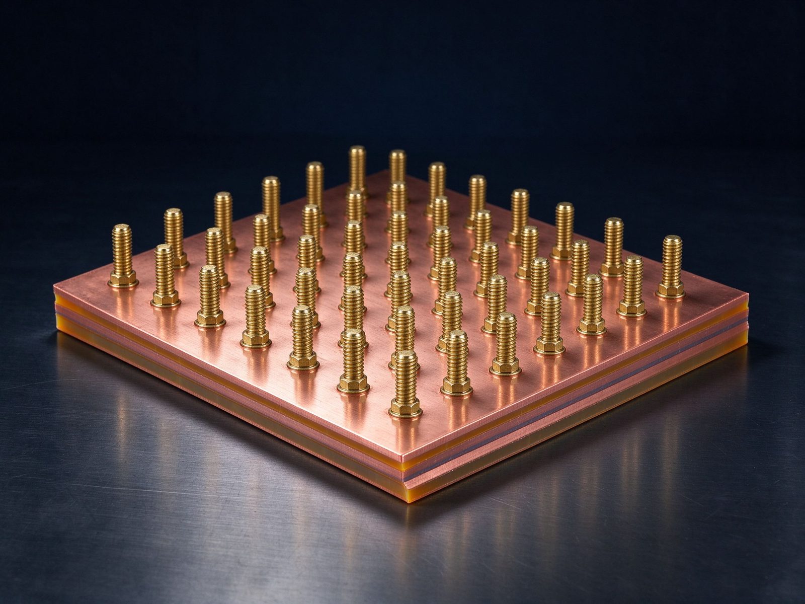
The part this application is built around — a SHANYUAN laminated busbar, factory direct.
Referenzfotos aus der SHANYUAN-Produktion und von versandten Baugruppen.
Ausgewählte Hinweise und Produktseiten, die die Design-Entscheidungen dieser Seite stützen.
Passende Stromschienen-Familien, die das Stromprofil dieser Anwendung tragen.
Laminierte Stromschiene für Leistungswandler mit seitlichen Fahnenanschlüssen und zentralem Montagebolzen.
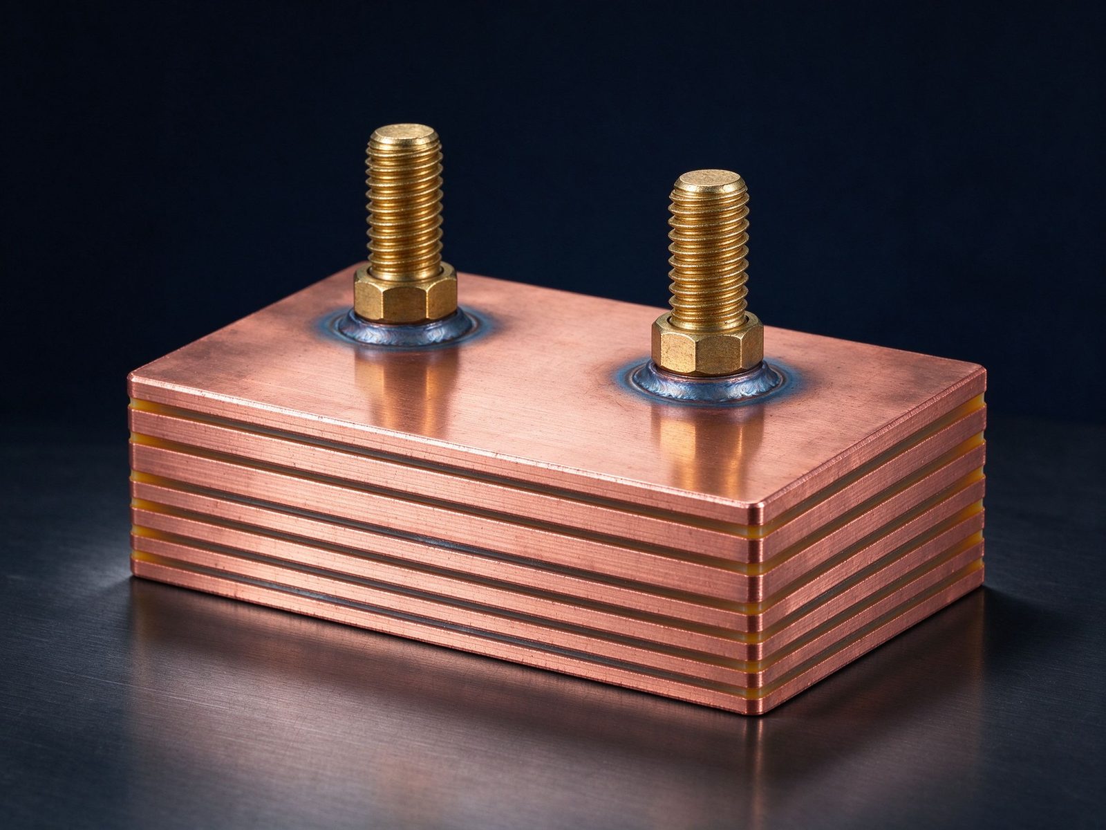
Geschweißte laminierte Stromschienen-Baugruppe für die Hochstrom-Leistungsverteilung mit vormontierten Anschlu
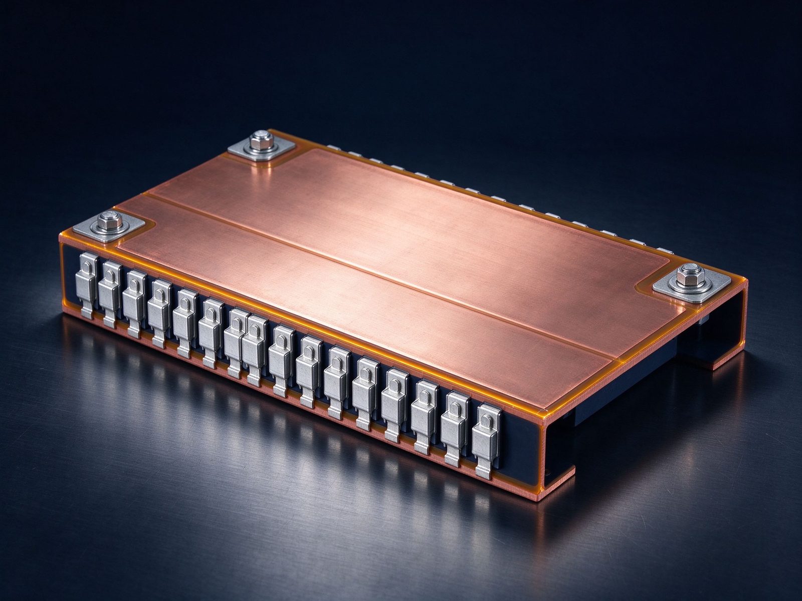
Laminierte Stromschiene für EV-Traktionsumrichter mit Messeranschlüssen für Hochspannungs-Architekturen.
Von der Spezifikationsprüfung bis zu versandten, geprüften Teilen – ein verantwortlicher Lieferant.
| Material | Standard options |
|---|---|
| Conductors | C11000 copper as standard; aluminum available on request |
| Dielectrics | PET, Nomex and epoxy (DLF) films, selected by voltage class and operating temperature |
| Plating | Tin finish for corrosion protection and joint solderability |
Aufbau, Dielektrikum-Auswahl und Grundlagen der Stromtragfähigkeit.
Design-Leitfaden lesenVoltage class, current profile and terminal types — we will share reference configurations and DFM guidance.
Klare Antworten vom Engineering-Team.
Send the application, voltage class and current profile — we will share reference configurations and DFM guidance.