Send a drawing or specification — our engineers review it for manufacturability, quote it, and deliver tooled, tested laminated busbars. Every dimension, terminal and dielectric is configurable.
積層バスバーは、お客様の筐体、端子、電流ループを中心に設計されます。既製品は妥協を強います;カスタム積層バスバーは、層数、導体幅、誘電体厚さ、端子位置が図面と正確に一致するよう金型化されます – 1部品、ゼロ手直し。
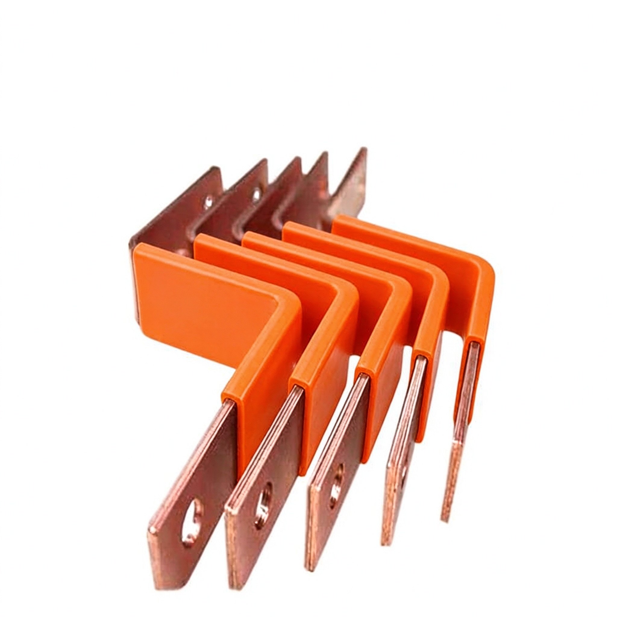
1 to 6+ conductors in one insulated stack, tuned to your current path.
C11000 copper as standard; aluminum available on request.
PET, Nomex or epoxy (DLF) selected by voltage class and temperature.
Tin as standard for corrosion resistance and solderability.
M6/M8 studs, blade tabs, screw and welded terminals, fused links.
Length, width, thickness, cut-outs and terminal windows to your drawing.
Integrated brackets, standoffs, edge seals and bolt-down ears.
Hipot, insulation, continuity, dimensional records, CoC and PPAP.
| Parameter | Range / Option |
|---|---|
| Conductor layers | 1 – 6+ (custom stack-ups) |
| Conductor material | C11000 copper (standard), aluminum on request |
| Plating | Tin (standard); alternative finishes by request |
| Dielectrics | PET, Nomex, epoxy (DLF) — selected by voltage class |
| Voltage class | 48 V to 1,200 V+ per your insulation coordination |
| Rated current | Up to ~1000 A per design (see ampacity chart) |
| Terminal types | M6/M8 threaded studs, blade tabs, screw, welded, fused links |
| Temperature rise | 30 °C reference; derated for ambient and enclosure |
| Mounting | Integrated brackets, standoffs, edge seals |
| Documentation | CoC, test records, PPAP-style on request |
Reference values are design starting points. Final specifications are defined in the quotation and released drawing for your project. See the busbar ampacity chart for current ratings and derating factors.
知っている項目を入力 – 残りはエンジニアにお任せ。選択内容は構造化された問い合わせにまとめられ、事前入力されたWhatsAppまたはメールが開きます。アカウント不要、ダウンロード不要。
Layer count recommendations for your voltage class and current.
Thermal class vs. dielectric strength, matched to your environment.
Placement checked against your enclosure and mating parts.
Inductance-oriented layout advice for switching circuits.
金型が切られる前に、当社エンジニアが図面のDFMレビューを実施します – 層数、電流経路、端子間隔、端部距離、誘電体クリアランス。この段階で端部距離の不足や溶接ゾーンの過小設計を発見する方が、生産中に見つけるよりはるかに安上がりです。
Stack-up validated against voltage class and current.
Cross-sections checked against continuous and peak current.
Pitch and weld zones matched to mating hardware.
Creepage and dielectric clearances verified before tooling.
The direction in high-current programs is that OEMs increasingly buy the laminated busbar not as a loose part but as part of a delivered subsystem — busbar plus connectors, flexible jumpers and cooling hardware integrated into one assembly. Reference market examples of this move are battery disconnect units (BDUs) for electrified powertrains and packaged power-conversion assemblies, where the supplier count shrinks and the line build becomes a drop-in installation rather than a harness build. For a custom laminated busbar design shop, this is the natural upward extension: the bar is already the backbone of the cabinet, so carrying terminals, jumpers and brackets along with it changes little at the drawing stage and a great deal on the customer’s floor.
The co-design principle behind it is that the busbar and its connector land are engineered together, not retrofitted. Industry datasheets specify the bar cross-section at every contact — for example a 38.1 × 4.8 mm copper land with an M6 thread at one frame size, and a 25.4 × 3.2 mm blade at another — and poles are paralleled in a single housing when a single contact cannot carry the current. Specifying the bar around the contact geometry is what makes blind-mate, hot-pluggable and service-friendly interfaces possible at all.
Four transferable design principles recur across this family of work:
When the joint itself moves — vibration, thermal expansion between module and bar — a flexible laminated jumper between rigid ends carries the motion without fatiguing the bolted joint, as explained in flexible laminated busbars. Whether you start from a drawing or from a current-path sketch, our DFM review turns the same principles against your layout; the process is outlined in the laminated busbar design guide, and reference stacked builds are shown under multi-layer insulated busbars.
エンジニアリングチームによる明確な回答。
Drawing or not — send the requirement and we will advise on the configuration.
