Send a drawing or specification — our engineers review it for manufacturability, quote it, and deliver tooled, tested laminated busbars. Every dimension, terminal and dielectric is configurable.
يُصمم قضيب التوصيل الرقائقي حول غلافك وأطرافك وحلقة تيارك. القضبان الجاهزة تفرض تنازلات؛ قضيب التوصيل الرقائقي المخصص يُصنع قوالبه بحيث تطابق الطبقات وعرض الموصل وسمك العازل ومواضع الأطراف رسمك تماماً – قطعة واحدة، بلا إعادة عمل.
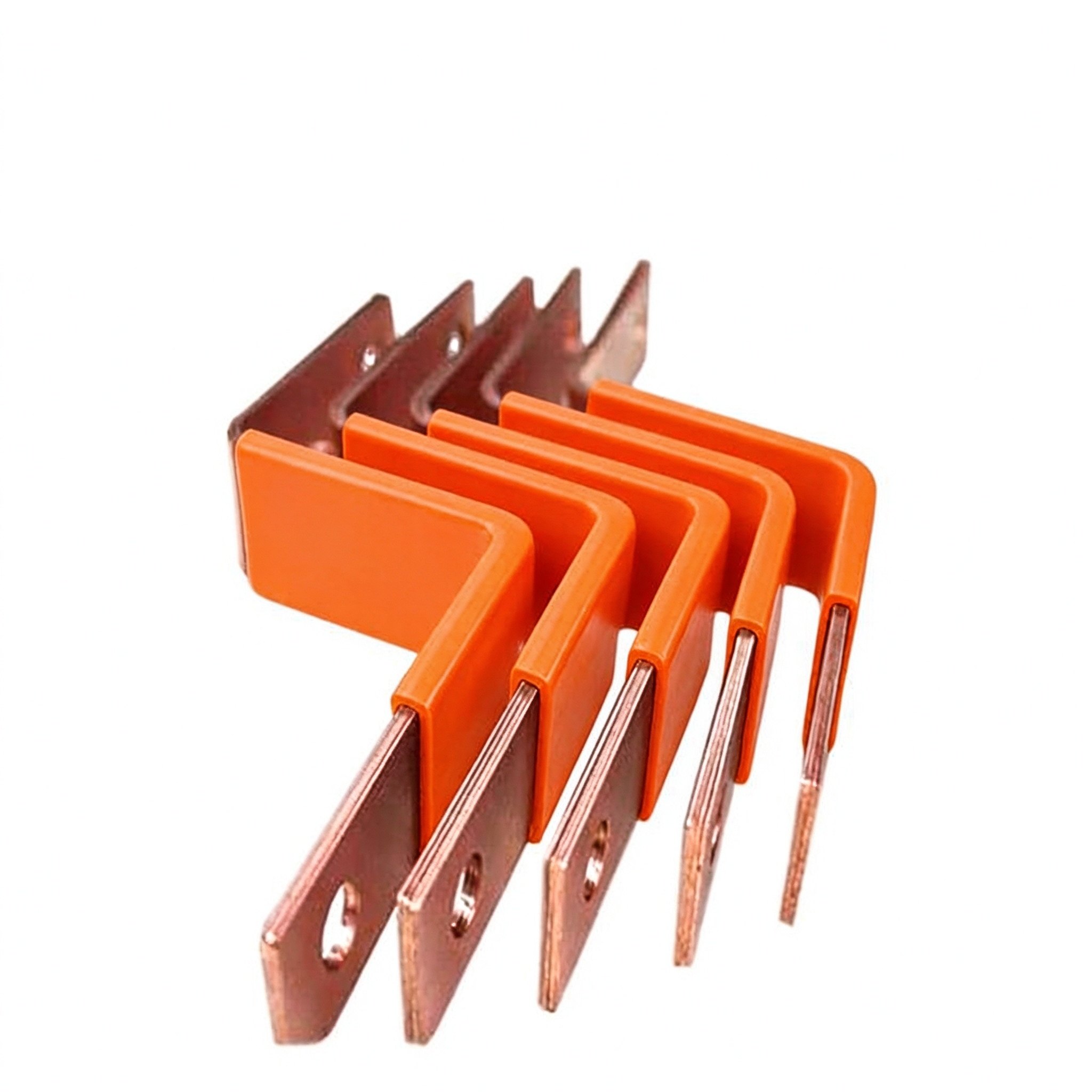
1 to 6+ conductors in one insulated stack, tuned to your current path.
C11000 copper as standard; aluminum available on request.
PET, Nomex or epoxy (DLF) selected by voltage class and temperature.
Tin as standard for corrosion resistance and solderability.
M6/M8 studs, blade tabs, screw and welded terminals, fused links.
Length, width, thickness, cut-outs and terminal windows to your drawing.
Integrated brackets, standoffs, edge seals and bolt-down ears.
Hipot, insulation, continuity, dimensional records, CoC and PPAP.
| Parameter | Range / Option |
|---|---|
| Conductor layers | 1 – 6+ (custom stack-ups) |
| Conductor material | C11000 copper (standard), aluminum on request |
| Plating | Tin (standard); alternative finishes by request |
| Dielectrics | PET, Nomex, epoxy (DLF) — selected by voltage class |
| Voltage class | 48 V to 1,200 V+ per your insulation coordination |
| Rated current | Up to ~1000 A per design (see ampacity chart) |
| Terminal types | M6/M8 threaded studs, blade tabs, screw, welded, fused links |
| Temperature rise | 30 °C reference; derated for ambient and enclosure |
| Mounting | Integrated brackets, standoffs, edge seals |
| Documentation | CoC, test records, PPAP-style on request |
Reference values are design starting points. Final specifications are defined in the quotation and released drawing for your project. See the busbar ampacity chart for current ratings and derating factors.
املأ ما تعرفه – واترك الباقي لمهندسينا. تُجمع اختياراتك في استفسار منظم وتفتح واتساب أو بريداً معبأ مسبقاً. لا حساب، لا تنزيل.
Layer count recommendations for your voltage class and current.
Thermal class vs. dielectric strength, matched to your environment.
Placement checked against your enclosure and mating parts.
Inductance-oriented layout advice for switching circuits.
قبل قطع أي قالب، يجري مهندسونا مراجعة DFM لرسمك – عدد الطبقات، مسارات التيار، تباعد الأطراف، مسافات الحواف وخلوص العازل. اكتشاف مسافة حافة ضيقة أو منطقة لحام صغيرة في هذه المرحلة أرخص بكثير من اكتشافها في الإنتاج.
Stack-up validated against voltage class and current.
Cross-sections checked against continuous and peak current.
Pitch and weld zones matched to mating hardware.
Creepage and dielectric clearances verified before tooling.
The direction in high-current programs is that OEMs increasingly buy the laminated busbar not as a loose part but as part of a delivered subsystem — busbar plus connectors, flexible jumpers and cooling hardware integrated into one assembly. Reference market examples of this move are battery disconnect units (BDUs) for electrified powertrains and packaged power-conversion assemblies, where the supplier count shrinks and the line build becomes a drop-in installation rather than a harness build. For a custom laminated busbar design shop, this is the natural upward extension: the bar is already the backbone of the cabinet, so carrying terminals, jumpers and brackets along with it changes little at the drawing stage and a great deal on the customer’s floor.
The co-design principle behind it is that the busbar and its connector land are engineered together, not retrofitted. Industry datasheets specify the bar cross-section at every contact — for example a 38.1 × 4.8 mm copper land with an M6 thread at one frame size, and a 25.4 × 3.2 mm blade at another — and poles are paralleled in a single housing when a single contact cannot carry the current. Specifying the bar around the contact geometry is what makes blind-mate, hot-pluggable and service-friendly interfaces possible at all.
Four transferable design principles recur across this family of work:
When the joint itself moves — vibration, thermal expansion between module and bar — a flexible laminated jumper between rigid ends carries the motion without fatiguing the bolted joint, as explained in flexible laminated busbars. Whether you start from a drawing or from a current-path sketch, our DFM review turns the same principles against your layout; the process is outlined in the laminated busbar design guide, and reference stacked builds are shown under multi-layer insulated busbars.
توزيع تيار عالٍ للرفوف وقضبان التوزيع والطاقة الاحتياطية.
إجابات مباشرة من فريق الهندسة.
Drawing or not — send the requirement and we will advise on the configuration.
