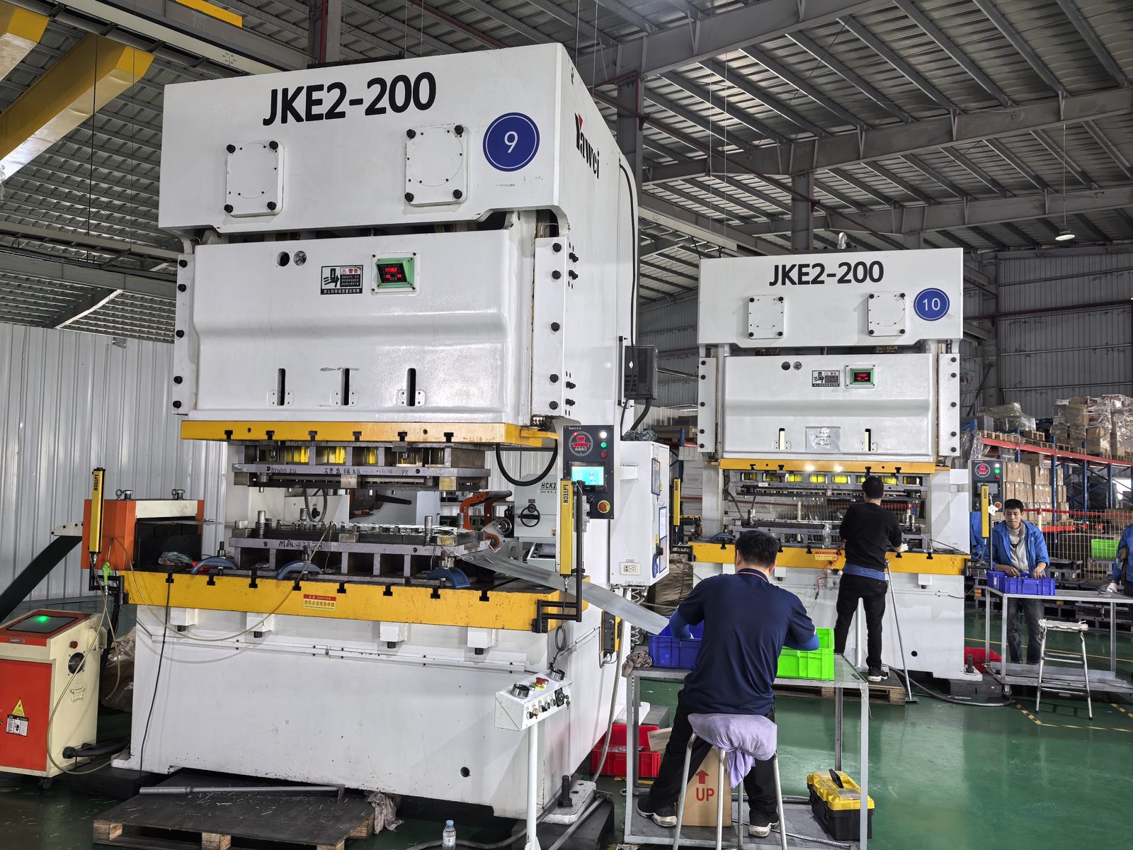
Propulsion converters for trains, trams and metros combine high voltage with high current and extreme environments. We engineer rail traction busbars that keep loop inductance and partial discharge under control where service continuity is non-negotiable.
The four places busbars carry current in this application.
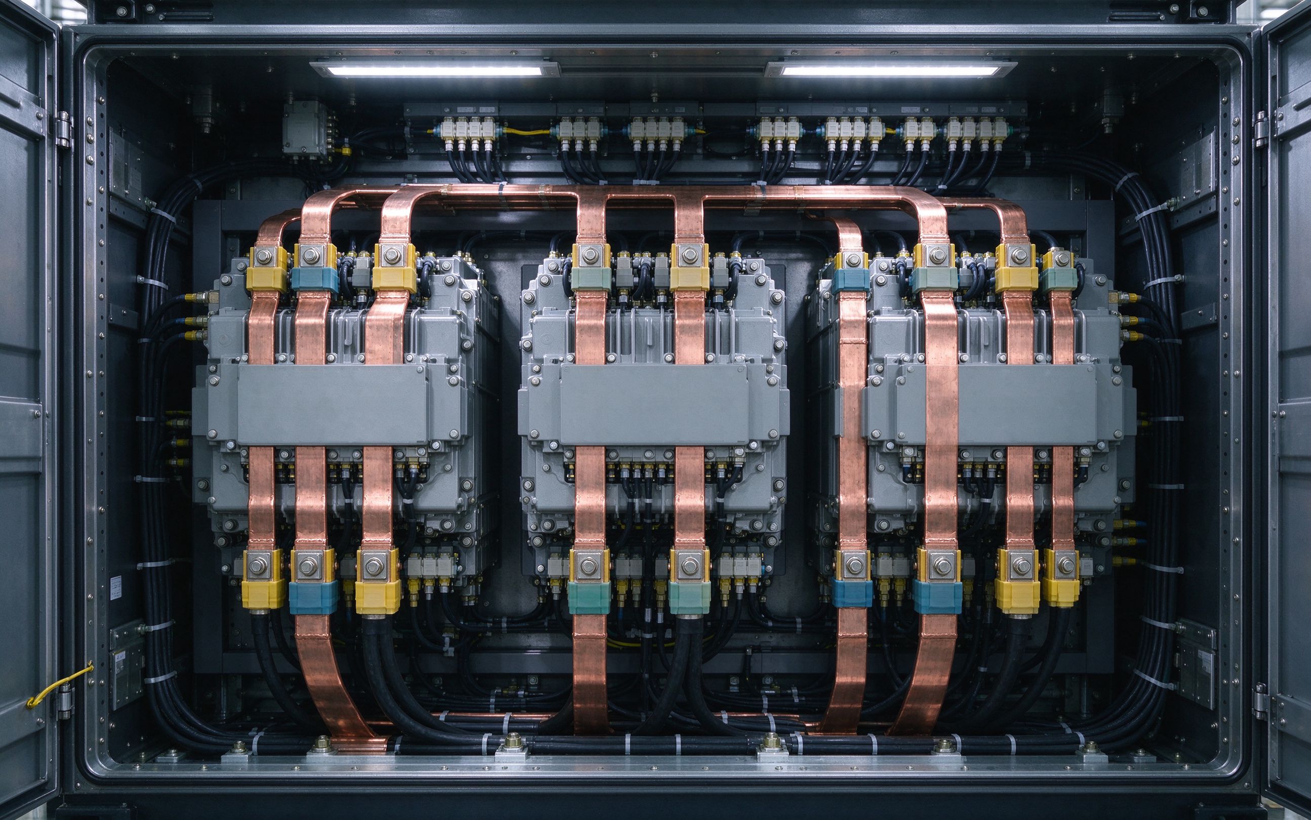
The laminated link between the DC feed (overhead line or onboard DC bus), DC-link capacitors and the IGBT stack of the main propulsion converter.
Low-inductance distribution feeding the auxiliary inverters that stabilize AC for on-board compressors, brakes and lighting.
Compact connections inside battery chargers that generate high-stability DC to charge vehicle batteries and feed other DC loads.
Form-fitting multilayer bars routing DC between line converter, brake chopper and motor inverter within one traction cabinet.
Short, rigid, high-current links to brake resistors that must withstand pulsed fault-energy duty.
Hybrid power+signal layouts carrying gate drive and temperature sense alongside the power plane where cabinet space is tight.
Tell us the line voltage and DC-link voltage plus required derating — dielectric selection and creepage/clearance follow from these.
On-board ambient range, humidity class, and any altitude or air-conditioning de-rate assumptions, at quotation.
Rail vibration and shock profiles drive flexible lamella sections at module interfaces — share your specification.
DC-link capacitor layout defines the commutation loop; share the capacitor position for an inductance-first layout.
We align batch test records, CoC and PPAP-style documentation with your quality system — tell us what your audit requires.
Propulsion systems for trains, trams and metros require high power — high current and high voltage combined with wide temperature swings, humidity and constant vibration. Operational continuity is essential: any shutdown in a traction converter has severe operational and financial consequences, so enhanced reliability dominates every development decision. A rail traction busbar sits at the heart of this power chain as the customized link between the DC source — the overhead line feed or onboard DC bus — and the IGBT modules of the complete converter.
Under IGBT switching, stray inductance shows up as voltage overshoot, V = L × di/dt. A properly engineered laminated stack provides the lowest overall system inductance and the most balanced, distributed capacitance, which is why the DC-link loop is designed around the busbar geometry rather than around bolted hardware. We build these assemblies as part of our power electronics busbars family: 1–6+ layers of C11000 copper, tin-plated and edge-sealed, sized up to ~1000 A per assembly with you.
On-board traction equipment runs hot and humid. Reference traction designs specify high-temperature dielectric systems rated up to 130 °C continuous versus 105 °C standard grades — the dielectric choice is the differentiator. Sealed edges, tight layer alignment and controlled creepage distances keep partial discharge below the industry reference level of 10 pC, the same PD discipline we explain in our laminated busbar design guide. Where vibration and thermal expansion meet the modules, flexible lamella sections absorb the stress that rigid bars would transfer into bolted joints. Auxiliary converters and on-board battery chargers use the same low-loss, low-inductance design at lower power, stabilizing AC for compressors, brakes and lighting. The same reliability-first, PD-controlled, derated long-life discipline carries over to military & aerospace busbars when our customers extend their converter platforms to defense or airborne programs.
Replacing hand-built buswork and cable harnesses with one tooled assembly removes wiring errors, shortens cabinet build time and raises short-circuit withstand. Conductor sizing starts from the reference current ratings in our busbar ampacity chart, then is derated for your actual ambient and enclosure. If you are designing a traction or auxiliary converter, start with the same DFM review process we use for every custom busbar program.
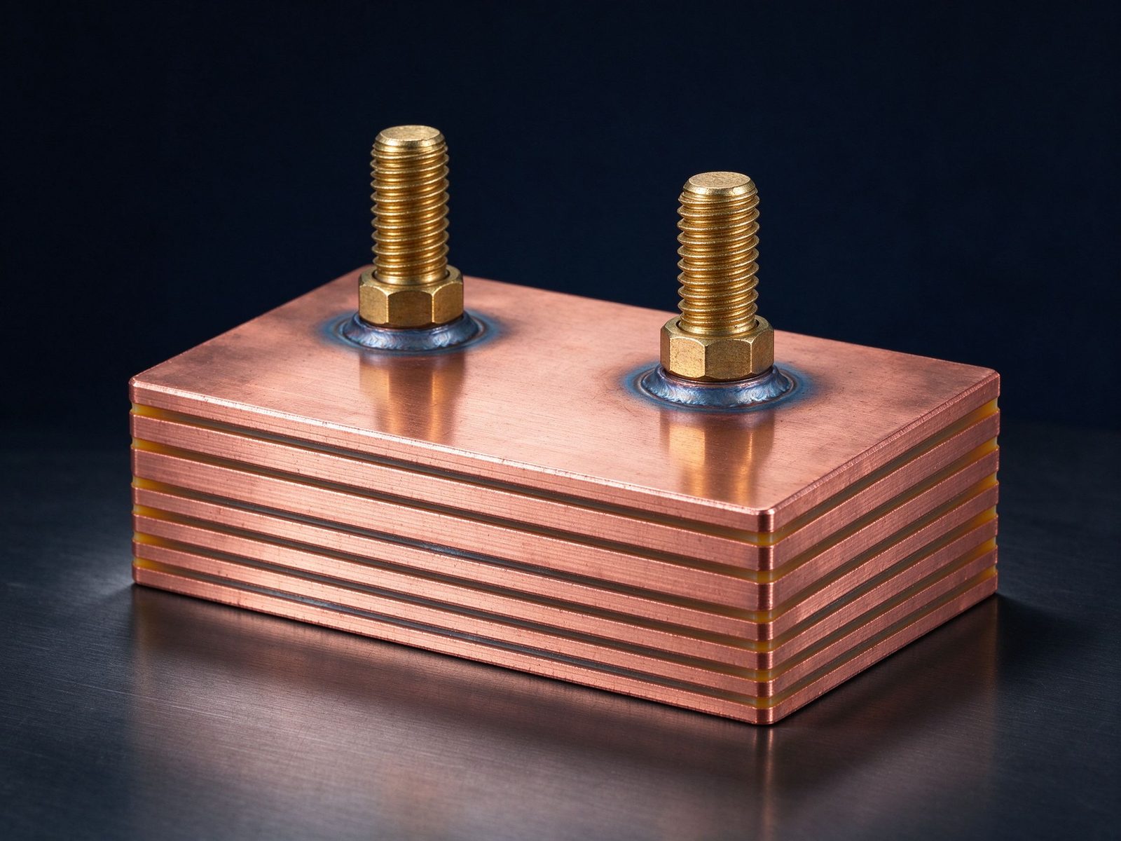
The part this application is built around — a SHANYUAN laminated busbar, factory direct.
Ảnh tham chiếu từ sản xuất SHANYUAN và các cụm lắp ráp đã xuất.
Các ghi chú và trang sản phẩm chọn lọc hỗ trợ các quyết định thiết kế trên trang này.
Các dòng thanh cái phù hợp đáp ứng biên độ dòng của ứng dụng này.
Cụm thanh cái ép lớp hàn để phân phối điện dòng cao với các chân đã hàn sẵn.
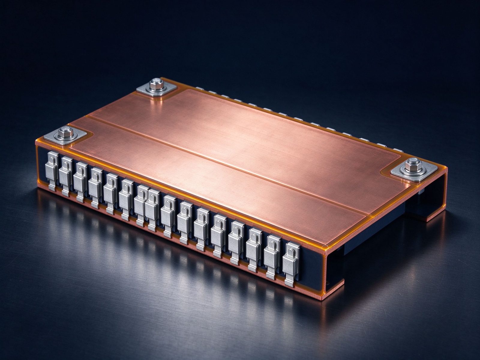
Thanh cái ép lớp cho biến tần truyền lực EV với đầu nối chân phẳng cho kiến trúc cao áp.
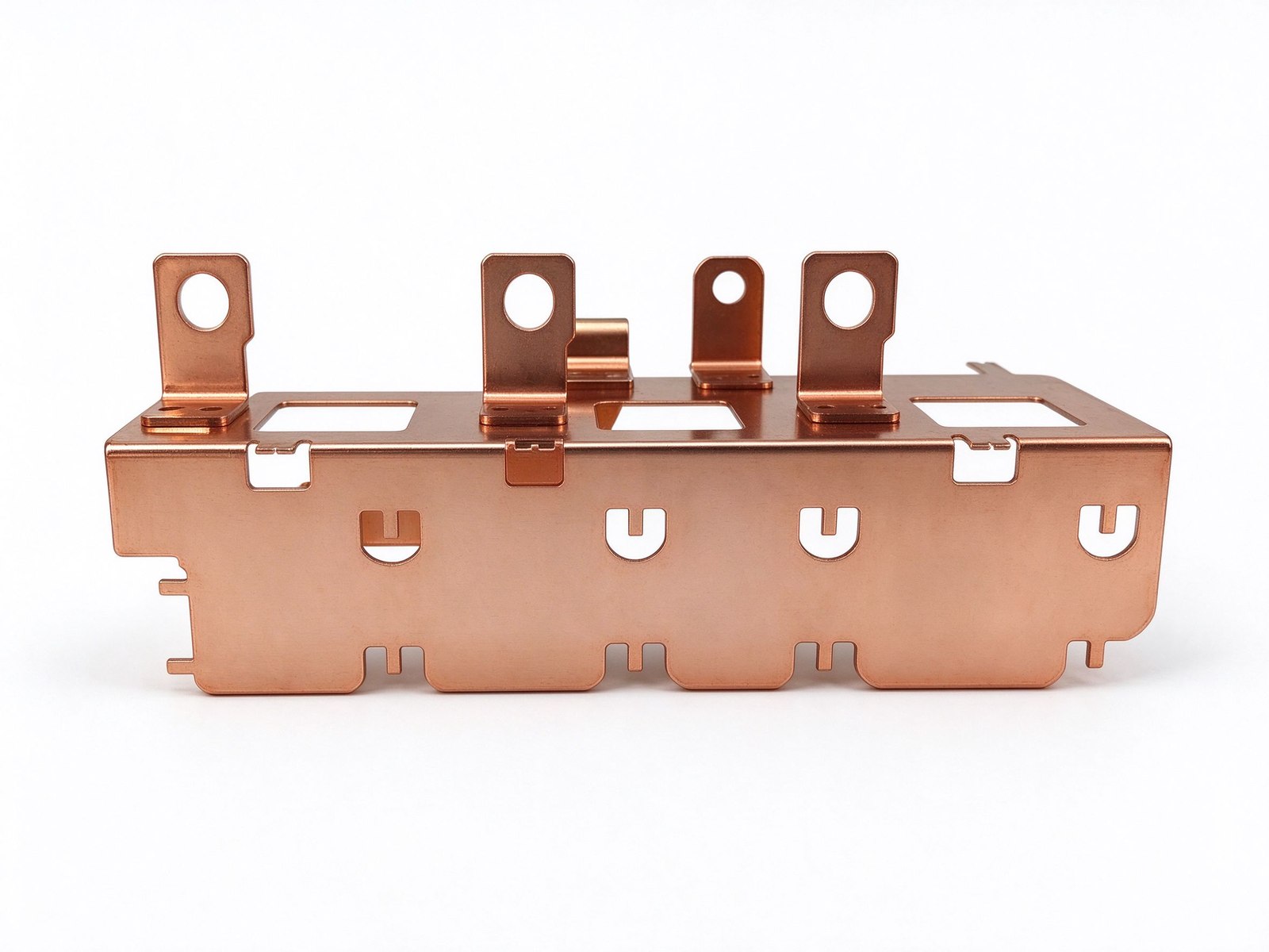
Từ rà soát thông số đến linh kiện giao hàng và kiểm thử – một nhà cung cấp chịu trách nhiệm.
| Material | Standard options |
|---|---|
| Conductors | C11000 copper as standard; aluminum available on request |
| Dielectrics | PET, Nomex and epoxy (DLF) films, selected by voltage class and operating temperature |
| Plating | Tin finish for corrosion protection and joint solderability |
Cấu trúc, chọn điện môi và cơ bản về khả năng dòng.
Đọc hướng dẫn thiết kếVoltage class, current profile and terminal types — we will share reference configurations and DFM guidance.
Câu trả lời thẳng thắn từ đội kỹ thuật.
Send the application, voltage class and current profile — we will share reference configurations and DFM guidance.