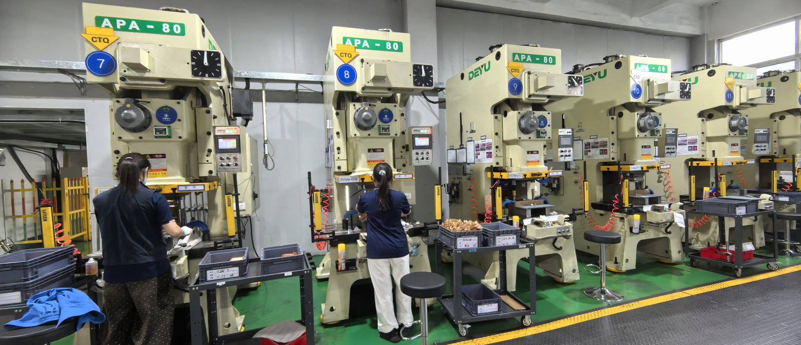
Fans, pumps, compressors and elevators run on variable-frequency drives. We build motor drive busbars that keep the DC link low-inductance and cool, inside shrinking drive enclosures.
The four places busbars carry current in this application.
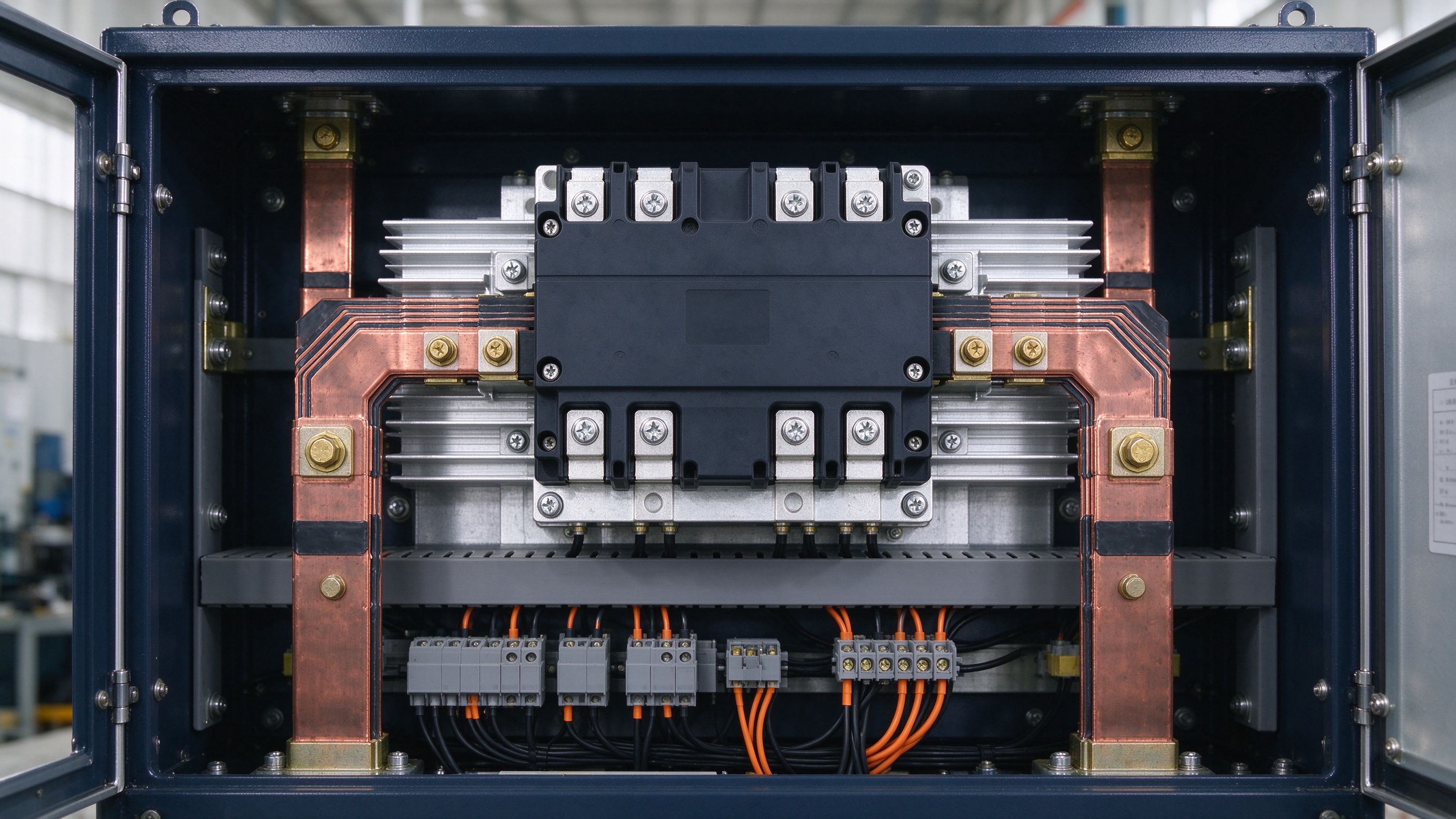
The laminated connection between the DC bus or capacitor bank and the IGBT phase-leg stack of the drive.
Matched busbar sets with blade tabs at module pin pitch — no adaptation hardware.
Multi-tab laminates sharing ripple current evenly across parallel DC-link capacitors.
Pulsed-duty connections feeding brake resistors during deceleration.
Low-impedance bars between the rectifier bridge and the DC bus in four-quadrant drives.
Thick-copper hybrid construction for drive stages that sit between PCB-only and full laminated territory.
Low-voltage (400–690 V class reference) or medium-voltage lineup — creepage and clearance follow.
Drive rating, overload duty cycle and braking current shape conductor sizing.
IGBT module datasheet pin pitch — terminals are matched to it to avoid adapters.
Enclosure ambient, forced air or liquid-cooled assumptions, at quotation.
Pump, fan or crusher duty — flexible lamella sections absorb vibration and thermal expansion where needed.
Electric motors — fans, pumps, compressors, elevators, refrigeration — consume the majority of industrial electricity, so even small efficiency gains in motor drives have large energy impact. Variable-frequency drives now provide speed and torque control, reduce wear by avoiding repeated starts and stops of pumps and valves, and cut total energy use. Drives improve as IGBT/MOSFET switches, gate drivers and bias supplies are integrated more tightly into the converter.
Inside the drive, laminated busbars act as the power-distribution highway — the customized link between the DC source or DC bus, the DC-link capacitors and the IGBT stack or complete power module. Flat, compact multilayer construction enables efficient, cool-running operation through low inductance, controlled partial discharge and high current capability. Where the current sits in the 100–500 A band — more than a standard PCB can carry, but below the territory of full laminated bars — reference designs use thick-copper hybrid construction (400–800 µm copper), wave-solderable like a PCB while carrying busbar-level current.
Loop inductance is the performance lever. Lower loop inductance means better switching performance and lower switching losses; stray inductance drives power component ratings, switching frequency and losses, which is why the commutation loop is designed around the busbar. Optimized busbar distribution through the IGBT/MOSFET modules is also the practical mitigation path for harmonic distortion — the kind that causes faulty meter readings, motor bearing failures, blown fuses and communication interference. Drive topologies keep shrinking in cost and size, which rewards the form-fitting geometry of laminated stacks.
We build these DC links as 1–6+ layer C11000 copper assemblies, tin-plated, edge-sealed, with blade tabs at your module datasheet pitch. Our laminated busbar design guide walks through layer-by-layer construction, and the busbar ampacity chart gives reference current ratings before derating for your enclosure. Medium-voltage lineups and lowest-inductance stages are covered in our power electronics busbars family, and the same derating and PD-control discipline extends to aerospace-grade laminated busbars when drives move into defense or airborne racks. Every drive DC link ships with per-lot hipot, PD and continuity test records aligned to your quality system. Send us the drive rating and module layout for DFM review — usually within one business day.
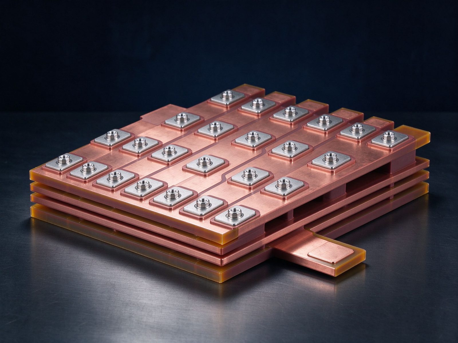
The part this application is built around — a SHANYUAN laminated busbar, factory direct.
Ảnh tham chiếu từ sản xuất SHANYUAN và các cụm lắp ráp đã xuất.
Các ghi chú và trang sản phẩm chọn lọc hỗ trợ các quyết định thiết kế trên trang này.
Các dòng thanh cái phù hợp đáp ứng biên độ dòng của ứng dụng này.
Bộ thanh cái ép lớp cho module công suất IGBT với đầu nối chân khớp cho các pha.
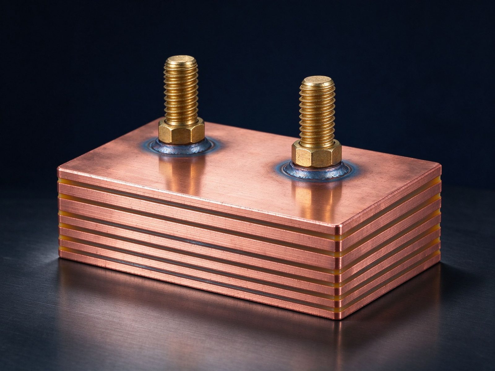
Cụm thanh cái ép lớp hàn để phân phối điện dòng cao với các chân đã hàn sẵn.
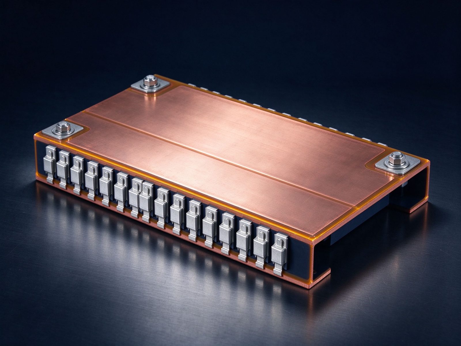
Thanh cái ép lớp cho biến tần truyền lực EV với đầu nối chân phẳng cho kiến trúc cao áp.
Từ rà soát thông số đến linh kiện giao hàng và kiểm thử – một nhà cung cấp chịu trách nhiệm.
| Material | Standard options |
|---|---|
| Conductors | C11000 copper as standard; aluminum available on request |
| Dielectrics | PET, Nomex and epoxy (DLF) films, selected by voltage class and operating temperature |
| Plating | Tin finish for corrosion protection and joint solderability |
Cấu trúc, chọn điện môi và cơ bản về khả năng dòng.
Đọc hướng dẫn thiết kếVoltage class, current profile and terminal types — we will share reference configurations and DFM guidance.
Câu trả lời thẳng thắn từ đội kỹ thuật.
Send the application, voltage class and current profile — we will share reference configurations and DFM guidance.