Nordwind Power Systems, a Danish converter manufacturer serving European onshore and offshore wind projects, contracted SHANYUAN in late 2025 to supply the DC-link capacitor-bank busbar for its 6 MW converter platform. The 6-layer laminated design reduced effective series inductance by 43%, held temperature rise to 24 °C at 2400 A, and included 4000 m altitude derating — a requirement driven by Andean wind projects.
This case study is published as a representative engineering project. The product photograph and released drawing are illustrative of the delivered part; exact dimensions are covered by the customer's non-disclosure agreement.
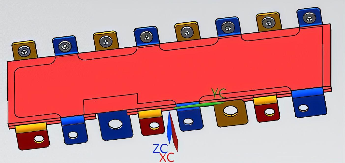
Customer drawings are treated as confidential; excerpts shown here are provided with permission and illustrate the layer stack, terminal layout and dielectric boundaries of the delivered part.
| Customer & platform | Nordwind Power 6 MW wind converter, 1500 V DC-link, 2400 A continuous |
|---|---|
| Busbar type | 6-layer laminated DC-link + capacitor-bank busbar, C11000 copper |
| Dielectric system | Nomex 410 + epoxy edge, PD-free to 2.4 kV, 4.8 kV hi-pot |
| ESL reduction | 43% lower effective series inductance vs the previous solid-copper layout |
| Dòng định mức | 2400 A continuous, 100% ripple current on capacitor section |
| Độ tăng nhiệt | ΔT 24 °C at rated current, measured on capacitor tabs |
| Terminals | Blade terminals for film capacitors, M10 studs for IGBT modules, silver-plated |
| Altitude rating | 4000 m derating per IEC 60068-2-13, creepage extended 30% |
| Quantified result | 43% lower ESL, 24 °C ΔT, PD-free to 2.4 kV, 4000 m altitude rated |
Nordwind Power Systems, a Danish converter manufacturer serving European onshore and offshore wind projects, contracted SHANYUAN in late 2025 to supply the DC-link capacitor-bank busbar for its 6 MW converter platform. The 6-layer laminated design reduced effective series inductance by 43%, held temperature rise to 24 °C at 2400 A, and included 4000 m altitude derating — a requirement driven by Andean wind projects.
Nordwind's 6 MW converter platform uses a three-level NPC topology with a 1500 V DC-link. During commissioning of the first prototypes, the engineering team measured higher-than-expected voltage ripple at the IGBT modules and saw elevated capacitor temperatures at full load. The root cause traced to the solid-copper busbar layout: the capacitor-bank connections were too far from the module commutation loops, adding series inductance that amplified ripple current stress.
The customer asked SHANYUAN to design a replacement DC-link busbar with two hard requirements: keep the existing mechanical envelope, and reduce effective series inductance enough to bring module voltage stress back inside the silicon derating curve. Our response started with a review of their released drawings against the low-inductance design guide, and a laminated busbar design guide DFM pass on layer count and terminal placement.
Ripple-current data from the customer's power-stage tests was used to size the copper section and confirm the capacitor connection scheme before any tooling was committed.
The final design uses six interleaved copper layers — three positive and three negative — arranged so that every capacitor tab sits directly above the corresponding IGBT module commutation loop. This stacked geometry cancels magnetic flux between layers and shortens the current path for each capacitor individually.
On the test bench, effective series inductance fell by 43% against the old solid-copper layout, and module voltage ripple at full switching frequency dropped into the silicon's safe operating area. The capacitor bank busbar product family documents this layer-interleaving pattern, and the power electronics busbar range carries the equivalent DC-link configurations.
Blade terminals for the film capacitors were machined with a 0.03 mm flatness target so that each capacitor connection carries its share of the ripple current evenly; joint resistance per tab was held below 40 μΩ.
Because Nordwind ships to high-altitude wind farms, the busbar had to be rated to 4000 m. Per IEC 60068-2-13, air pressure at 4000 m is roughly 61% of sea level, so creepage distances were extended by 30% and the partial-discharge test voltage was derated accordingly. The insulation system — Nomex 410 film with epoxy edge sealing — remains PD-free to 2.4 kV at sea level and 2.0 kV at altitude.
Dielectric selection followed the design guide voltage-class rules, and the full PD test method is documented in the partial-discharge resource. Thermal testing measured 24 °C temperature rise at 2400 A in a 50 °C ambient chamber, with the hot spot on the capacitor tabs; forced-air cooling in the converter cabinet holds operating temperature comfortably inside the PET/Nomex rating.
Creepage and clearance tables used for this project are the same reference values published in the ampacity chart and the thermal management guide.
Prototypes were delivered in week six, and the customer's power-stage test bench confirmed the ESL and ripple improvements within the first two test days. Qualification followed a 12-week PPAP plan: 4.8 kV hi-pot, 500 thermal cycles from −40 °C to +105 °C, and vibration per IEC 61373 category 2 for turbine-mounted electronics.
Series production runs in batches of 120 parts with 100% hi-pot and inductance scan per part, mirroring the process used for our other solar and wind applications. The quality laboratory issues a per-batch test dossier covering ESL, PD and thermal-rise measurements, which Nordwind's quality team accepts without additional audits.
The customer's procurement team also used our supplier evaluation guide during the initial shortlisting; the full wind converter busbar demand article explains why converter OEMs are moving to laminated DC-links in this power class.
The delivered busbar met every target on the customer's test bench: 43% lower effective series inductance, 24 °C temperature rise at 2400 A, PD-free to 2.4 kV at sea level and 2.0 kV at 4000 m altitude, and joint resistance below 40 μΩ per capacitor tab.
Module voltage stress returned inside the silicon derating curve at full switching frequency, and the converter passed type testing in the first attempt — the customer reported that the busbar change removed the need for a module derating step that had been planned for the 4000 m variant.
For engineers designing wind or PV converter DC-links, the solar and wind application page, the low-inductance guide and the SHANYUAN engineering desk are the fastest route to a first-pass layout.
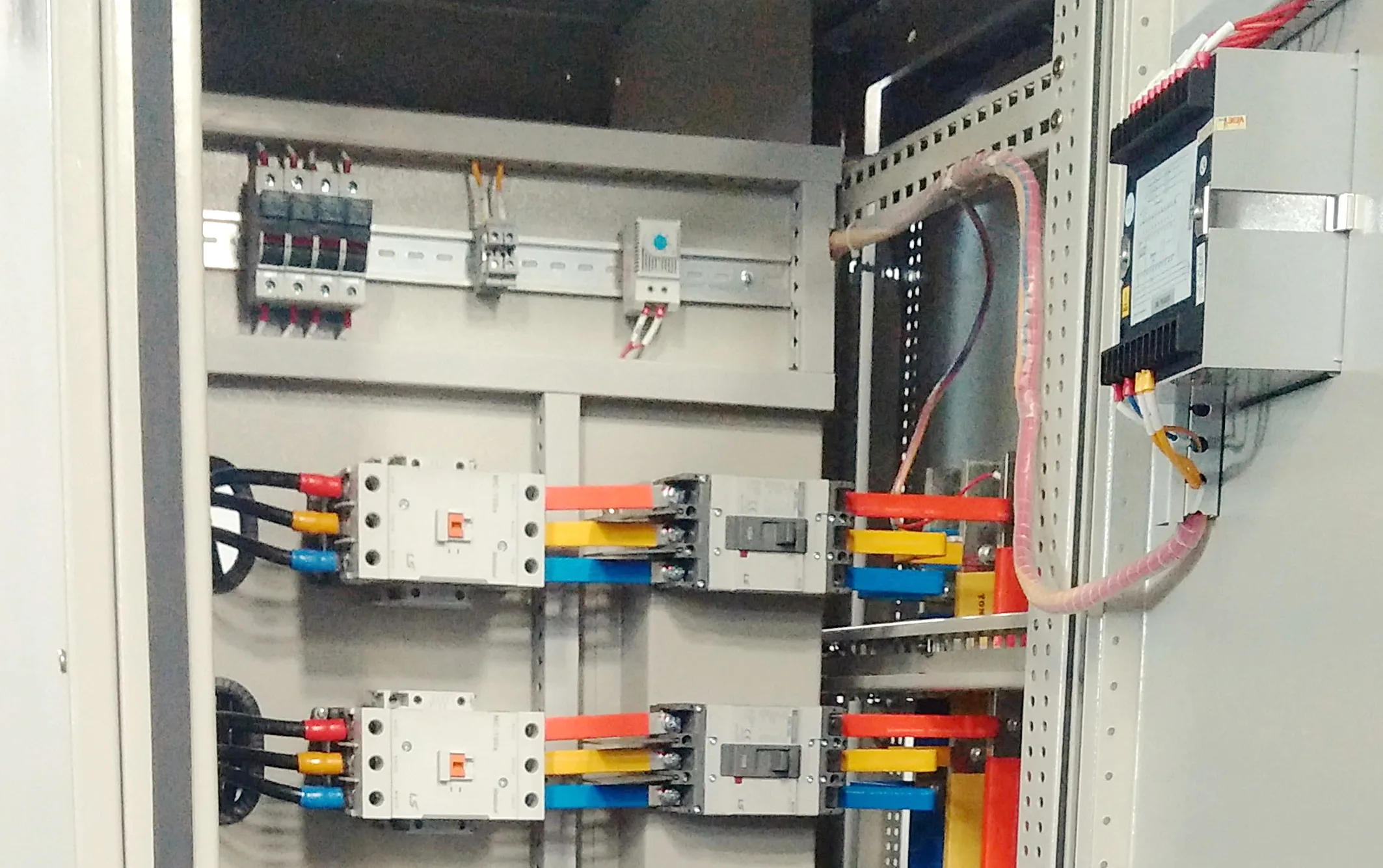
Turbin lon hon nghia la stack cong suat lon hon, va do thanh dan DC-link cua gon
Đọc bài viết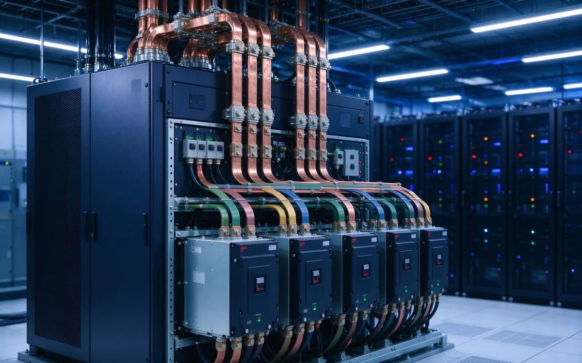
BloombergNEF thấy 158-188 GW lưu trữ mới trong 2026. Các nền tảng PCS đang leo t
Đọc bài viết
Elena Vasquez là kỹ sư ứng dụng điện tử công suất với 10 năm kinh nghiệm tích hợp thanh cái ép lớp vào bộ biến tần xe điện, hệ thống sạc và PCS lưu trữ năng lượng. Cô chuyên thiết kế liên kết DC điện cảm thấp, hành vi EMC và đóng gói bộ biến đổi. Cô có bằng Cử nhân Kỹ thuật điện tại Đại học Bách kho
Gửi hồ sơ dòng điện, cấp điện áp và loại đầu nối — kỹ sư của chúng tôi trả lời trong một ngày làm việc.