VoltCharge Systems, an Italian manufacturer of high-power EV chargers, engaged SHANYUAN in 2026 for the DC-link busbar inside its 350 kW charger power cabinet. The laminated interconnect — 12 nH loop inductance, 600 A per module, hot-plug tolerant — passed 5000 connector cycles and supports the 800 V output stage deployed across EU fast-charging corridors.
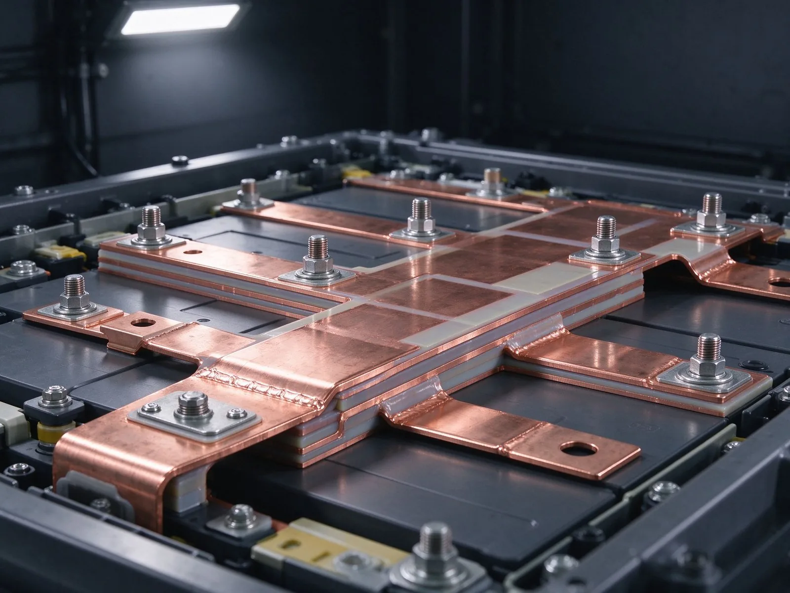
This case study is published as a representative engineering project. The product photograph and released drawing are illustrative of the delivered part; exact dimensions are covered by the customer's non-disclosure agreement.
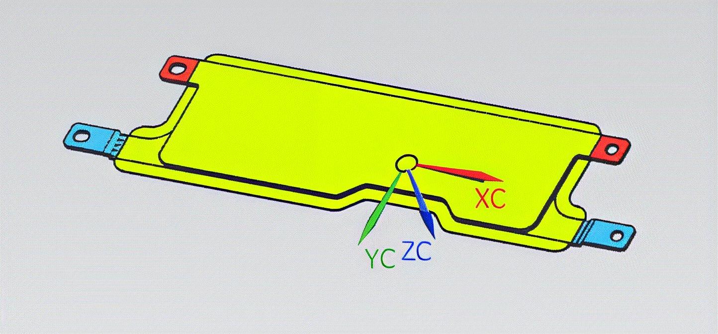
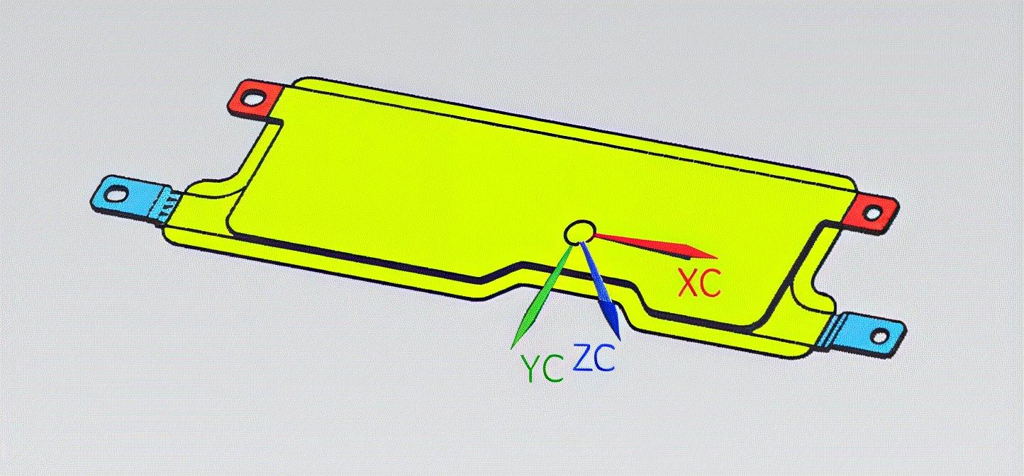
Customer drawings are treated as confidential; excerpts shown here are provided with permission and illustrate the layer stack, terminal layout and dielectric boundaries of the delivered part.
| Customer & platform | VoltCharge 350 kW DC fast charger, 800 V output, six 60 kW power modules |
|---|---|
| Busbar type | Laminated DC-link busbar, C11000 copper, interleaved layers |
| Dielectric system | PET film, 1.8 kV hi-pot, hot-plug tolerant insulation |
| Loop inductance | 12 nH measured at module terminals |
| التيار المقنن | 600 A per module, 750 A peak |
| ارتفاع درجة الحرارة | ΔT 24 °C at rated current, 55 °C cabinet ambient |
| Terminals | Blind-mate frame connectors + M8 studs, tin-plated |
| Production | EU-wide deployment support, 100% inductance scan |
| Quantified result | 12 nH, 5000-cycle hot-plug, 24 °C ΔT, 600 A/module |
VoltCharge Systems, an Italian manufacturer of high-power EV chargers, engaged SHANYUAN in 2026 for the DC-link busbar inside its 350 kW charger power cabinet. The laminated interconnect — 12 nH loop inductance, 600 A per module, hot-plug tolerant — passed 5000 connector cycles and supports the 800 V output stage deployed across EU fast-charging corridors.
VoltCharge's 350 kW charger cabinet holds six 60 kW power modules that are designed to be hot-swapped in the field — a module is pulled and replaced while the other five keep charging. Each module connects to a shared DC-link busbar through a blind-mate frame connector. The challenge was to keep loop inductance low enough for the SiC modules while allowing repeated blind-mate insertion without damaging the busbar or the connector.
Test data from the customer's prototype phase showed that a conventional bolted busbar could not meet the 15 nH inductance budget once the blind-mate connectors were included. SHANYUAN was asked to design the DC-link busbar and connector interface together, within a 12-week sample cycle.
The design followed the low-inductance design guide, with the connector interface engineered to the busbar connections guide — clip contact physics, not just bolted joints.
The delivered busbar interleaves positive and negative layers across the full length, ending in a connector zone where each module's blind-mate frame engages spring-loaded blade contacts. Measured loop inductance at the module terminals is 12 nH — inside the 15 nH budget — with the connector contributing only 1.4 nH.
The contact zone uses the multi-point clip pattern documented in the connections guide: each module connection has six independent contact points per polarity, so a single imperfect blade does not break the connection. The blade terminal busbar assembly product family carries this pattern.
Hot-plug tolerance comes from the spring-loaded contact geometry plus a controlled insertion angle; 5000 insertion cycles on the test rig produced no measurable change in contact resistance (stable at 0.9 mΩ per module connection).
Temperature-rise testing at 600 A per module in a 55 °C cabinet ambient measured 24 °C rise at the connector zone — the hottest point — inside the 28 °C budget. The thermal management guide documents the cabinet airflow assumptions.
The insulation system is PET film with a 1.8 kV hi-pot rating, sized for the 800 V output stage with headroom for grid transients. Creepage across the connector zone follows the terminal machining guide clearance rules, and the exposed contact area is minimised so a live bus inspection is safe.
Ripple from the six paralleled modules was simulated against the layer stack; interleaving keeps the module-to-module coupling below 3 nH, which the customer's EMC test confirmed.
Production runs in cabinet kits with 100% inductance scanning per part, mirroring the automated production line practice. Each kit ships with a per-module inductance map so field service can verify a replacement module's connection after installation.
The quality laboratory executed the 5000-cycle connector test and the 1.8 kV hi-pot campaign; the test dossiers were accepted by the customer's EU charging-infrastructure certification body as part of the charger's EN 61851-23 file. The ultra-fast charging network article explains the deployment context.
Field data from the first 200 cabinets shows zero busbar-related failures in six months of operation across EU fast-charging corridors.
The delivered busbar met every target: 12 nH loop inductance, 600 A per module with 24 °C rise in 55 °C ambient, 5000 hot-plug cycles without contact-resistance drift, and a 1.8 kV hi-pot rating.
Hot-swap time per module is under 15 minutes including torque audit, and the blind-mate design removed the need for a cabinet shutdown during module replacement — a direct uptime benefit for a charger serving multiple vehicles.
For fast-charging hardware engineers, the EV charging application page, the power electronics busbar range and the engineering contact form are the entry points we recommend.
دفعة شحن BYD الوميض 2.0 تدفع 1.5 ميجاواط عبر مسدس مفرد عند 1000 فولت و1500 أمبير
اقرأ المقال
ينتقل MCS من التجربة إلى نطاق الأساطيل في 2026: شحن 1 ميجاواط+ عند 1250 فولت وحت
اقرأ المقال
إيلينا فاسكيز مهندسة تطبيقات الإلكترونيات الكهربائية بخبرة 10 سنوات في دمج قضبان التوصيل الرقائقية في محولات السيارات الكهربائية وأنظمة الشحن وأنظمة تخزين الطاقة PCS. تتخصص في تصميم وصلات DC منخفضة الحث، وسلوك التوافق الكهرومغناطيسي، وتغليف المحولات. حاصلة على بكالوريوس الهندسة الكهربائية من جامعة م
أرسل ملف التيار وفئة الجهد وأنواع الأطراف — يرد مهندسونا خلال يوم عمل واحد.